DM183021 Microchip Technology, DM183021 Datasheet - Page 17
DM183021
Manufacturer Part Number
DM183021
Description
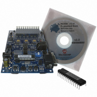
BOARD DEV PICDEM MC LV
Manufacturer
Microchip Technology
Series
PICDEM™r
Specifications of DM183021
Main Purpose
Power Management, Motor Control
Embedded
No
Utilized Ic / Part
PIC18F, dsPIC30F
Primary Attributes
Brushless DC (BLDC) Motors, 3-Phase, 1A, LIN, SPI, PWM Interface
Secondary Attributes
Graphical User Interface
Silicon Manufacturer
Microchip
Silicon Core Number
PIC18F2431, DsPIC30F3010
Core Architecture
PIC
Core Sub-architecture
PIC18F, PIC30F
Silicon Family Name
Piccolo
Lead Free Status / RoHS Status
Lead free / RoHS Compliant
Available stocks
Company
Part Number
Manufacturer
Quantity
Price
Company:

Part Number:
DM183021
Manufacturer:
Microchip Technology
Quantity:
135
Company:
Part Number:
DM183021
Manufacturer:
MICROCHIP
Quantity:
12 000


2.4
© 2006 Microchip Technology Inc.
POWER INVERTER SECTION
2.3.4
Hall sensors on the motor are open-collector outputs. Individual pull-up resistors are
provided on the board for each Hall sensor. The Hall sensor signals, HA, HB and HC,
are connected to the input capture pins, IC1, IC2 and IC3, respectively.
2.3.5
When a sensorless algorithm is used to control the BLDC motor speed, Back EMF
(BEMF) signals are used. Based on zero crossing of BEMF signals, motor com-
mutation is decided in the firmware. The signal conditioning circuit has mainly two
blocks: the first is a low-pass filter for each phase voltage and the second is a
comparator circuit for determining the zero crosspoint. When using the PIC18F MCU,
the jumpers are set to use both of these blocks. The output is connected to the input
capture pins, IC1, IC2 and IC3. When a dsPIC30F DSC is used, the low-pass filters are
used in the circuit. Using the on-chip Analog-to-Digital Converters, the BEMF zero
crosspoint is determined. In order to configure this, the board has 8 jumpers. Refer to
Chapter 3. “Getting Started with PIC18FXX31 MCUs” and Chapter 6. “Getting
Started with dsPIC Digital Signal Controllers” for jumper settings for the PIC18F
and dsPIC30F, respectively. Also, refer to Appendix C. “Jumper Settings” for the
complete list of jumper settings. In addition, the silk screen on the non-component side
of the board has the jumper settings printed for quick reference.
2.3.6
A temperature sensor is placed next to the PCB heat sink near Q5. The sensor,
Microchip’s TC74, has an I
to a digital value. This value can be read using the I
does not include the temperature reading routines. The routines for the Master mode
I
The inverter section consists of three half-bridge gate drivers and three phase inverter
bridges using MOSFETs. Figure 2-2 shows a half-bridge gate driver and half-bridge
inverter. This circuit is repeated for each motor phase winding. PWM pairs,
PWM0-PWM1, PWM2-PWM3 and PWM4-PWM5, control three half-bridge inverters.
The DC bus is either derived from the 24V power supply connected to the input
connector J20, or from the ‘+’ and ‘–’ terminals on connector J9.
FIGURE 2-2:
2
C, using the SSP module, can be found on Microchip’s web site.
Note:
Hall Sensor Interface
Back EMF Signal Conditioning
Temperature Measurement Circuit
When using the temperature sensor, jumpers J16 and J17 should be open.
When the temperature sensor is used, LEDs D2 and D3 are not available.
System Level Architecture of the Board
HALF-BRIDGE GATE DRIVER AND INVERTER
PWM1
PWM0
2
C™ interface. It measures the temperature and converts it
IR2101
Driver
PWM1
PWM0
2
C protocol. The code on the CD
Q1
Q0
DC+
DC-
M1
DS51554B-page 13
Related parts for DM183021
Image
Part Number
Description
Manufacturer
Datasheet
Request
R

Part Number:
Description:
Manufacturer:
Microchip Technology Inc.
Datasheet:
Part Number:
Description:
Manufacturer:
Microchip Technology Inc.
Datasheet:
Part Number:
Description:
Manufacturer:
Microchip Technology Inc.
Datasheet:
Part Number:
Description:
Manufacturer:
Microchip Technology Inc.
Datasheet:
Part Number:
Description:
Manufacturer:
Microchip Technology Inc.
Datasheet:
Part Number:
Description:
Manufacturer:
Microchip Technology Inc.
Datasheet:
Part Number:
Description:
Manufacturer:
Microchip Technology Inc.
Datasheet:
Part Number:
Description:
Manufacturer:
Microchip Technology Inc.
Datasheet: