DM183021 Microchip Technology, DM183021 Datasheet - Page 30
DM183021
Manufacturer Part Number
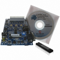
DM183021
Description
BOARD DEV PICDEM MC LV
Manufacturer
Microchip Technology
Series
PICDEM™r
Specifications of DM183021
Main Purpose
Power Management, Motor Control
Embedded
No
Utilized Ic / Part
PIC18F, dsPIC30F
Primary Attributes
Brushless DC (BLDC) Motors, 3-Phase, 1A, LIN, SPI, PWM Interface
Secondary Attributes
Graphical User Interface
Silicon Manufacturer
Microchip
Silicon Core Number
PIC18F2431, DsPIC30F3010
Core Architecture
PIC
Core Sub-architecture
PIC18F, PIC30F
Silicon Family Name
Piccolo
Lead Free Status / RoHS Status
Lead free / RoHS Compliant
Available stocks
Company
Part Number
Manufacturer
Quantity
Price
Company:

Part Number:
DM183021
Manufacturer:
Microchip Technology
Quantity:
135
Company:
Part Number:
DM183021
Manufacturer:
MICROCHIP
Quantity:
12 000


PICDEM™ MC LV Development Board
DS51554B-page 26
5. Disconnect the power supply and ensure that the jumper settings and motor
TABLE 6-1:
TABLE 6-2:
6. Keep the potentiometer “REF” on the 50% or center position. Turn the pot
7. Connect the 24V power supply to the board. The red LED D7 will turn on.
8. To start the motor, press S2.
9. To increase the speed of the motor, turn the potentiometer marked “REF”
10. If the motor stops, press S2 once to reset the process and repeat steps 9-11.
11. The debug information will be relayed via the serial port. Connect Hyperterminal
J7, J11, J13
J15
J8, J10, J12, J14
J19
J16, J17
M1
M2
M3
G
+5V
Return (symbol)
HA
HB
HC
Label on Connector J9
Note 1:
connection match Table 6-1 and Table 6-2 respectively.
marked “R60” to the full clockwise position.
clockwise.
at 19200 baud to view the speed of the motor, or any Fault which occurs during
the execution of the code.
Jumper
2:
When programming the dsPIC device on the PICDEM MC LV Develop-
ment Board, the two DIP switches must be in the PRGM position. This
will ensure the programming pins are connected to the programmer. If the
user has generated independent code, the user must select
EMUC2/EMUD2 pins for emulation in the MPLAB Configuration menu.
These alternate pins will then be programmed and will be used for the
debugging or run phase.
After programming the dsPIC device, the user can disconnect the pro-
grammer from the ICD 2 plug J6 and run the device in Stand-Alone mode.
Alternatively, if the ICD 2 is being used in the Emulator mode, then the
DIP switches have to be switched to the DEBUG position. Then, the
EMUC2/EMUD2 pins will be connected to the ICD 2, and assuming the
configuration was done as described above, the user will be able to run
the firmware using the ICD 2 as an emulator.
JUMPER SETTINGS
MOTOR CONNECTIONS
Open
Don’t care
Open
Short
Short
Phase C (red)
Phase B (black)
Phase A (white)
Ground (green)
Power-on Hall Sensor (red)
Power Return for Hall Sensor (black)
Hall S1 (white)
Hall S2 (brown)
Hall S3 (green)
Sensored Control
Sensored Control
WARNING
© 2006 Microchip Technology Inc.
Short between 2-3
Don’t care
Open
Open
Short
Phase C (red)
Phase A (white)
Phase B (black)
Ground (green)
No Connection
No Connection
No Connection
No Connection
No Connection
Sensorless Control
Sensorless Control
Related parts for DM183021
Image
Part Number
Description
Manufacturer
Datasheet
Request
R

Part Number:
Description:
Manufacturer:
Microchip Technology Inc.
Datasheet:
Part Number:
Description:
Manufacturer:
Microchip Technology Inc.
Datasheet:
Part Number:
Description:
Manufacturer:
Microchip Technology Inc.
Datasheet:
Part Number:
Description:
Manufacturer:
Microchip Technology Inc.
Datasheet:
Part Number:
Description:
Manufacturer:
Microchip Technology Inc.
Datasheet:
Part Number:
Description:
Manufacturer:
Microchip Technology Inc.
Datasheet:
Part Number:
Description:
Manufacturer:
Microchip Technology Inc.
Datasheet:
Part Number:
Description:
Manufacturer:
Microchip Technology Inc.
Datasheet: