DM183021 Microchip Technology, DM183021 Datasheet - Page 16
DM183021
Manufacturer Part Number
DM183021
Description
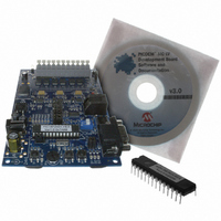
BOARD DEV PICDEM MC LV
Manufacturer
Microchip Technology
Series
PICDEM™r
Specifications of DM183021
Main Purpose
Power Management, Motor Control
Embedded
No
Utilized Ic / Part
PIC18F, dsPIC30F
Primary Attributes
Brushless DC (BLDC) Motors, 3-Phase, 1A, LIN, SPI, PWM Interface
Secondary Attributes
Graphical User Interface
Silicon Manufacturer
Microchip
Silicon Core Number
PIC18F2431, DsPIC30F3010
Core Architecture
PIC
Core Sub-architecture
PIC18F, PIC30F
Silicon Family Name
Piccolo
Lead Free Status / RoHS Status
Lead free / RoHS Compliant
Available stocks
Company
Part Number
Manufacturer
Quantity
Price
Company:

Part Number:
DM183021
Manufacturer:
Microchip Technology
Quantity:
135
Company:
Part Number:
DM183021
Manufacturer:
MICROCHIP
Quantity:
12 000


PICDEM™ MC LV Development Board
2.3
DS51554B-page 12
CONTROL SECTION
Microchip’s PIC18F2431/2331 and many versions of the dsPIC30F DSCs have
specialized hardware peripherals, like the power control PWM, high-speed ADC,
motion control feedback, integrated EEPROM and the power supervisory function, that
are required for efficient motor control. The CD supplied along with the PICDEM MC LV
Development Board has a variety of programs using both PIC18F and dsPIC30F
devices, working in open loop and closed loop, using Hall sensors and in sensorless
operation. Chapter 3. “Getting Started with PIC18FXX31 MCUs” explains the con-
trol algorithm using PIC18F parts and Chapter 6. “Getting Started with dsPIC Digital
Signal Controllers” explains the control algorithm for dsPIC30F parts.
2.3.1
The PICDEM MC LV Development Board has two 28-pin DIP sockets, one each for the
PIC18F2331/2431 MCUs and dsPIC30F2010/3010 DSCs. They are offset to each
other and marked as the “PIC” and “dsPIC” sockets, respectively. When shipped, a
preprogrammed PIC18F2431 is mounted on the “PIC” side of U1. To use the dsPIC
device, the user has to remove the PIC18F from the socket and mount the dsPIC DSC
on the “dsPIC” side of U3.
Apart from the main controller, the control section has protection circuitry, user interface,
Hall sensor interface and Back EMF (BEMF) signal conditioning for sensorless control.
2.3.2
A shunt resistor (R26 = 0.1Ω) connected in the DC return path converts the combined
three-phase motor current into voltage. This voltage is passed through a low-pass filter
and amplified using an op amp circuit with a gain of 11. This amplified voltage is connected
to one of the Analog-to-Digital Converter channels (AN0). In addition to this, the amplified
voltage is compared to a voltage reference using an op amp comparator. The voltage ref-
erence is set using potentiometer R60. Turning the potentiometer clockwise increases the
reference and counterclockwise reduces the reference. The range of voltage reference
varies from 0V to 3.3V. Based on the motor rated current, the reference can be set. A test
point “MOTOR” is given to monitor the motor current on an oscilloscope.
2.3.3
On the PICDEM MC LV Development Board, there are switches, LEDs and a
potentiometer to use with the GUI interface. Table 2-1 describes each function.
TABLE 2-1:
Switch
S1
S2 and S3
LED
D1, D2, D3
PWM0-PWM5
Potentiometer R14
Board Function
Controller Sockets
Overcurrent Protection Circuit
User Interface
USER INTERFACE
Used for resetting the system
Various functions
Display status
Display status of PWM0-PWM5
Motor speed control
Description
See Chapter 3. “Getting Started
with PIC18FXX31 MCUs” and
Chapter 6. “Getting Started with
dsPIC Digital Signal Controllers”.
See Chapter 6. “Getting Started
with dsPIC Digital Signal Control-
lers” and Chapter 3. “Getting
Started with PIC18FXX31 MCUs”.
Turning the potentiometer clockwise
increases the speed and vice versa.
© 2006 Microchip Technology Inc.
Comments
Related parts for DM183021
Image
Part Number
Description
Manufacturer
Datasheet
Request
R

Part Number:
Description:
Manufacturer:
Microchip Technology Inc.
Datasheet:
Part Number:
Description:
Manufacturer:
Microchip Technology Inc.
Datasheet:
Part Number:
Description:
Manufacturer:
Microchip Technology Inc.
Datasheet:
Part Number:
Description:
Manufacturer:
Microchip Technology Inc.
Datasheet:
Part Number:
Description:
Manufacturer:
Microchip Technology Inc.
Datasheet:
Part Number:
Description:
Manufacturer:
Microchip Technology Inc.
Datasheet:
Part Number:
Description:
Manufacturer:
Microchip Technology Inc.
Datasheet:
Part Number:
Description:
Manufacturer:
Microchip Technology Inc.
Datasheet: