ATDVK90CAN1 Atmel, ATDVK90CAN1 Datasheet - Page 9
ATDVK90CAN1
Manufacturer Part Number
ATDVK90CAN1
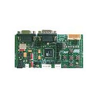
Description
KIT DEV FOR AT90CAN128 MCU
Manufacturer
Atmel
Specifications of ATDVK90CAN1
Main Purpose
*
Embedded
*
Utilized Ic / Part
AT90CAN AVR Devices
Primary Attributes
*
Secondary Attributes
*
Processor To Be Evaluated
AT90CAN
Data Bus Width
8 bit
Interface Type
RS-232, SPI, TWI
Core Architecture
AVR
Core Sub-architecture
AVR UC3
Kit Contents
Board, AT90CAN128 Sample Microcontroller, 9V Battery Power Cable, CD-ROM, Manuals
Features
RS232, CAN, LIN, SPI & TWI Serial Interface
Rohs Compliant
Yes
Lead Free Status / RoHS Status
Contains lead / RoHS non-compliant
Available stocks
Company
Part Number
Manufacturer
Quantity
Price
Company:

Part Number:
ATDVK90CAN1
Manufacturer:
Atmel
Quantity:
135


DVK90CAN1 Hardware User Guide
JACK PWR connector:
EXT PWR connector:
STK500 Powered: (c.f.
Figure 3-2 . JACK PWR Connector
Figure 3-3 . Male JACK Outlet and Wires
Caution: Do not mount more than one power supply source on DVK90CAN1.
Figure 3-4 . EXT PWR On-Board Male Connector
Figure 3-5 . EXT PWR Female Connector / Cable for 9V Battery
Notes:
-
– Need of a male JACK outlet,
– Input supply from 2.7 up to 15V
– No specific polarization
– Need of a female 2 points connector,
– Input supply from 2.7 up to 15V
– Polarization mandatory,
“STK500 Resources” on page 32
+
Pin
1. 15V is the maximum level limitation of an unidirectional transil diode.
2. There is a diode (bridge) voltage level between the negative output of the power
3. Caution: Do not mount more than one power supply source on DVK90CAN1.
1
2
supply and the DVK90CAN1 “GND”. This could introduce some gap of voltage during
measurement and instrumentation.
Name
Pwr +
Pwr -
+
-
(2)
mandatory.
).
+
-
(1)
(1)
+
DC,
DC (example: 9V battery),
+
-
-
Using the DVK90CAN1
4381A–AVR–Sept 04
+
-
page 7
Related parts for ATDVK90CAN1
Image
Part Number
Description
Manufacturer
Datasheet
Request
R

Part Number:
Description:
DEV KIT FOR AVR/AVR32
Manufacturer:
Atmel
Datasheet:

Part Number:
Description:
INTERVAL AND WIPE/WASH WIPER CONTROL IC WITH DELAY
Manufacturer:
ATMEL Corporation
Datasheet:
Part Number:
Description:
Low-Voltage Voice-Switched IC for Hands-Free Operation
Manufacturer:
ATMEL Corporation
Datasheet:
Part Number:
Description:
MONOLITHIC INTEGRATED FEATUREPHONE CIRCUIT
Manufacturer:
ATMEL Corporation
Datasheet:
Part Number:
Description:
AM-FM Receiver IC U4255BM-M
Manufacturer:
ATMEL Corporation
Datasheet:
Part Number:
Description:
Monolithic Integrated Feature Phone Circuit
Manufacturer:
ATMEL Corporation
Datasheet:
Part Number:
Description:
Multistandard Video-IF and Quasi Parallel Sound Processing
Manufacturer:
ATMEL Corporation
Datasheet:
Part Number:
Description:
High-performance EE PLD
Manufacturer:
ATMEL Corporation
Datasheet:
Part Number:
Description:
8-bit Flash Microcontroller
Manufacturer:
ATMEL Corporation
Datasheet:
Part Number:
Description:
2-Wire Serial EEPROM
Manufacturer:
ATMEL Corporation
Datasheet: