ATDVK90CAN1 Atmel, ATDVK90CAN1 Datasheet - Page 32
ATDVK90CAN1
Manufacturer Part Number
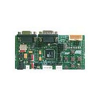
ATDVK90CAN1
Description
KIT DEV FOR AT90CAN128 MCU
Manufacturer
Atmel
Specifications of ATDVK90CAN1
Main Purpose
*
Embedded
*
Utilized Ic / Part
AT90CAN AVR Devices
Primary Attributes
*
Secondary Attributes
*
Processor To Be Evaluated
AT90CAN
Data Bus Width
8 bit
Interface Type
RS-232, SPI, TWI
Core Architecture
AVR
Core Sub-architecture
AVR UC3
Kit Contents
Board, AT90CAN128 Sample Microcontroller, 9V Battery Power Cable, CD-ROM, Manuals
Features
RS232, CAN, LIN, SPI & TWI Serial Interface
Rohs Compliant
Yes
Lead Free Status / RoHS Status
Contains lead / RoHS non-compliant
Available stocks
Company
Part Number
Manufacturer
Quantity
Price
Company:

Part Number:
ATDVK90CAN1
Manufacturer:
Atmel
Quantity:
135


4381A–AVR–Sept 04
Using the DVK90CAN1
3.7.8
page 30
Luminosity Sensor
Figure 3-36 . Thermistor Schematic
Figure 3-37 . Thermistor Implementation
The luminosity sensor uses a CdS photoconductive cell, or luminosity-sensitive resistor.
The luminosity-sensitive resistor have a negative coefficient, meaning the resistance
goes up as luminosity goes down. This luminosity sensor have a linear
resistance/temperature curve from 0 up to 75°C.
The luminosity sensor used in DVK90CAN1 has a resistance close to 60 K
and 5 K at 100 lux for a wavelength of 550 nm.
Table 3-16 . CdS Photoconductive Cell Electrical characteristics at temp=25°C
The voltage over the luminosity sensor can be found using the A/D converter. See the
AT90CAN128 Datasheet for how to use the ADC. The resistor value (R
Peak Spectral Wavelength
Parameter (
Light Resistance
Dark Resistance
temp=25°C
)
Min
20
20
550
Typ Max Units
5
100
K
K
K
nm
R31 = Thermistor
DVK90CAN1 Hardware User Guide
10 s after removal of light
10 s after removal of light
Test Conditions
100 lux
10 lux
L
) is calculate
at 10 lux
Related parts for ATDVK90CAN1
Image
Part Number
Description
Manufacturer
Datasheet
Request
R

Part Number:
Description:
DEV KIT FOR AVR/AVR32
Manufacturer:
Atmel
Datasheet:

Part Number:
Description:
INTERVAL AND WIPE/WASH WIPER CONTROL IC WITH DELAY
Manufacturer:
ATMEL Corporation
Datasheet:
Part Number:
Description:
Low-Voltage Voice-Switched IC for Hands-Free Operation
Manufacturer:
ATMEL Corporation
Datasheet:
Part Number:
Description:
MONOLITHIC INTEGRATED FEATUREPHONE CIRCUIT
Manufacturer:
ATMEL Corporation
Datasheet:
Part Number:
Description:
AM-FM Receiver IC U4255BM-M
Manufacturer:
ATMEL Corporation
Datasheet:
Part Number:
Description:
Monolithic Integrated Feature Phone Circuit
Manufacturer:
ATMEL Corporation
Datasheet:
Part Number:
Description:
Multistandard Video-IF and Quasi Parallel Sound Processing
Manufacturer:
ATMEL Corporation
Datasheet:
Part Number:
Description:
High-performance EE PLD
Manufacturer:
ATMEL Corporation
Datasheet:
Part Number:
Description:
8-bit Flash Microcontroller
Manufacturer:
ATMEL Corporation
Datasheet:
Part Number:
Description:
2-Wire Serial EEPROM
Manufacturer:
ATMEL Corporation
Datasheet: