P0006 Terasic Technologies Inc, P0006 Datasheet - Page 16
P0006
Manufacturer Part Number
P0006
Description
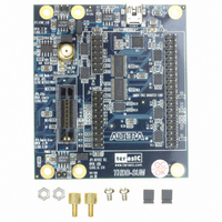
BOARD ADAPTER THDB-SUM
Manufacturer
Terasic Technologies Inc
Datasheet
1.P0006.pdf
(26 pages)
Specifications of P0006
Accessory Type
Adapter Board
For Use With/related Products
Board with HSMC Connector
Lead Free Status / RoHS Status
Lead free / RoHS Compliant
Available stocks
Company
Part Number
Manufacturer
Quantity
Price
Company:

Part Number:
P0006
Manufacturer:
Terasic Technologies Inc
Quantity:
135


This section describes the USB On-The-Go transceiver on the THDB-SUM board
The THDB-SUM is equipped with a NXP ISP1504C USB On-The-Go transceiver (U11) and Mini USB AB type
receptacle connector (J8) to provide USB interface to the HSMC interface host board. The ISP1504 is a
Universal Serial Bus (USB) On-The-Go (OTG) transceiver that is fully compliant with Universal Serial Bus
Specification Rev. 2.0, On-The-Go Supplement to the USB 2.0 Specification Rev. 1.3 and UTMI+ Low Pin
Interface (ULPI) Specification Rev. 1.1.
The pervious section, Santa Cruz Connector, has mentioned that USB transceiver and Santa Cruz connector
share the I/Os which connect to HSMC connector, which means users can only choose one function between
USB and Satan Cruz interface, If users would like to choose the function of USB transceiver, please turn on
JP2. For more detailed information about this transceiver, please refer to the datasheet which can be found in
the NXP’s website.
In addition, for OTG implementations, a 2-pin header named JP1 is connected with ID (identification) pin of
the USB OTG transceiver and micro-USB receptacle. As shown in
the USB OTG transceiver can be configured to logic high or low via JP1. As defined in On-The-Go supplement
to the USB 2.0 specification Rev. 1.3, the ID pin dictates the initial role of the link. If ID is detected as HIGH,
the link must assume the role of a peripheral. If ID is detected as LOW, the link must assume a
host role.
Finally, the detailed pin mappings between the USB On-The-Go transceiver and the HSMC connector are
shown in Table3.8.
Table 3.7
shows the JP1 configuration setting for the ID.
Table 3.7 The configuration of the ID pin
JP2 setting
Open
Close
3.3
USB On-The-Go transceiver
Host or peripheral role
Peripheral
Host
Figure
3.8, The logic level of the ID pin on
Related parts for P0006
Image
Part Number
Description
Manufacturer
Datasheet
Request
R

Part Number:
Description:
MODULE DIGITAL CAMERA 5MP (D5M)
Manufacturer:
Terasic Technologies Inc
Datasheet:

Part Number:
Description:
DE2-70 CALL FOR ACADEMIC PRICING
Manufacturer:
Terasic Technologies Inc
Datasheet:

Part Number:
Description:
USB BLASTER CABLE
Manufacturer:
Terasic Technologies Inc
Datasheet:

Part Number:
Description:
BOARD ADAPTER HSMC TO GPIO
Manufacturer:
Terasic Technologies Inc
Datasheet:

Part Number:
Description:
KIT DEV 4.3" LCD TOUCH PANEL
Manufacturer:
Terasic Technologies Inc
Datasheet:

Part Number:
Description:
DAUGHTER BOARD AD/DA GPIO ADA
Manufacturer:
Terasic Technologies Inc

Part Number:
Description:
DAUGHTER BOARD AD/DA HSMC ADA
Manufacturer:
Terasic Technologies Inc

Part Number:
Description:
KIT MAX II MICRO
Manufacturer:
Terasic Technologies Inc
Datasheet:

Part Number:
Description:
BOARD DEV/EDUCATION ALTERA DE0
Manufacturer:
Terasic Technologies Inc
Datasheet:

Part Number:
Description:
BOARD DEV DE1 ALTERA
Manufacturer:
Terasic Technologies Inc
Datasheet:

Part Number:
Description:
DE2 CALL FOR ACADEMIC PRICING
Manufacturer:
Terasic Technologies Inc

Part Number:
Description:
MODULE DIGITAL CAMERA 1.3MP
Manufacturer:
Terasic Technologies Inc
Datasheet:

Part Number:
Description:
SENSOR CMOS 1.3MEGA (FOR P0349)
Manufacturer:
Terasic Technologies Inc
Datasheet:
Part Number:
Description:
MODULE DIGITAL CAMERA 5MP (D5M)
Manufacturer:
Terasic Technologies Inc
Datasheet: