FPSS1U TDK Corporation, FPSS1U Datasheet - Page 46
FPSS1U
Manufacturer Part Number
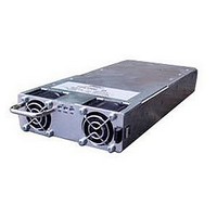
FPSS1U
Description
RACK 3 SLOT FOR FPS1000
Manufacturer
TDK Corporation
Series
FPSr
Specifications of FPSS1U
Accessory Type
Rack System
No. Of Slots
3
Peak Reflow Compatible (260 C)
No
External Width
19.00"
Rack U Height
1
External Depth
13.82"
For Use With
285-1239 - PWR SUP FNT END 48V 1008W 21A285-1238 - PWR SUP FNT END 32V 992W 31A285-1237 - PWR SUP FNT END 24V 960W 40A
Lead Free Status / RoHS Status
Lead free / RoHS Compliant
For Use With/related Products
FPS1000 Series
Lead Free Status / Rohs Status
RoHS Compliant part
Other names
285-1240
Available stocks
Company
Part Number
Manufacturer
Quantity
Price
Company:

Part Number:
FPSS1U
Manufacturer:
TDK-LAMBDA
Quantity:
232
Company:
Part Number:
FPSS1U/P
Manufacturer:
TDK-LAMBDA
Quantity:
232


17.7.5 Rear Panel In/Out Connector Pins Function Description
J1(A), J2(B), J3(C) CONECTOR DESCRIPTION
MALE HEADER:
FEMALE HOUSING (PLUG):
FEMALE TERMINAL:
Note:
*1: On/Off_1 and On/Off_2 are reversed logic inputs.
Pin No
10
11
12
13
14
15
16
1
2
3
4
5
6
7
8
9
SDA (I
SCL (I
SIGNAL_RETURN Return for the following control and supervisory signals: On/Off, DC_OK, Over_temperature
ON/OFF_2 (*1)
DC_OK
V_TRIM
-SENSE
+SENSE
+12V_AUX
CS
AC_FAIL
ON/OFF_1 (*1)
TEMP_ALARM
- LOCAL SENSE
+ LOCAL SENSE
Function
ON/OFF LOGIC
2
2
C)
C)
SELECT
FPS1000 unit is ≥85Vrms. The maximum sink current is 10mA, and the maximum external
Alarm, AC_Fail, Auxiliary 12V supply. The Signal return is isolated from the output terminals.
Connection for output voltage trimming of FPS1000 unit. The voltage can be trimmed within
Negative sensing. The -Sense signal should be connected to the negative terminal of the load.
The -Sense and +Sense leads should be twisted pair to minimize noise pick-up effect. The
maximum load wires drop compensation is 1V/wire.
Positive sensing. The +Sense signal should be connected to the positive terminal of the load.
The +Sense and -Sense leads should be twisted pair to minimize noise pick-up effect. The
maximum load wires drop compensation is 1V/wire.
Open collector signal, referenced to pin 3 (Signal Return). On when the input voltage of
Description
Serial Data used in the I
FPS1000 Instruction Manual.
Serial Clock used in the I
FPS1000 Instruction Manual.
On/Off control. To use this input, pin#12 and pin#13 must be shorted together.
Short between On/Off_2 to pin#3: Off. Open On/Off_2: On.
The maximum source current is 1.2mA
Open collector signal, referenced to pin 3 (Signal Return). On when the output
voltage of FPS1000 unit is higher than Vout ≥ 80% +/-5%. The maximum sink current:
10mA and the maximum external voltage is 15V.
its range specifications.
Auxiliary voltage output, 11.2~12.5V, referenced to pin 3 (Signal Return). The maximum
load current is 0.25A. This output is not controlled by the On/Off control.
Current sharing signal. When FPS1000 units are connected in parallel, the CS pins of the
units should be connected to allow current balance between units.
voltage is 15Vdc.
Turns the output of FPS1000 unit to On and Off by electrical signal or dry contact between
pin 12 and pin 3 (Signal Return). 0~0.6V or Short: On, 2~15V or Open: Off.
The maximum sink current is 2.6 mA (when using pin#12, it should be disconected from pin#13).
Input used to select the On/Off control logic.
Short this input to pin#12 when using On/Off_2 as On/Off control.
Leave this input open when using On/Off_1 as On/Off control.
Open collector signal, referenced to pin 3 (Signal Return). On when the internal temperature
of FPS1000 unit is within safe limit, Off approx. 10°C below Thermal shut down. The maximum
sink current is 10mA and the maximum external voltage is 15V.
When working in local sense mode, connect -Local Sense to -Sense (pin#7).
When working in Remote sense mode, this input should be open.
When working in local sense mode, connect +Local Sense to +Sense (pin#8).
When working in Remote sense mode, this input should be open.
P/N-43045-1600 (MOLEX)
P/N-43025-1600 (MOLEX)
P/N-43030 (MOLEX)
Rear In/Out connector pins function description (J1), (J2), (J3)
2
2
C interface option. Refer to the I
C interface option. Refer to the I
43
CONNECTOR PINOUT (REAR PANEL VIEW)
16
8
J1(A), J2(B), J3(C)
FPS-T1U Instruction Manual
2
C interface description in the
2
C interface description in the
9
1
Related parts for FPSS1U
Image
Part Number
Description
Manufacturer
Datasheet
Request
R

Part Number:
Description:
KIT F-SERIES CLIPS
Manufacturer:
PHIHONG USA
Datasheet:

Part Number:
Description:
TDK DC to DC Converters, DC to AC Inverters
Manufacturer:
TDK Corporation
Datasheet:
Part Number:
Description:
TDK DC to DC Converters, DC to AC Inverters
Manufacturer:
TDK Corporation
Datasheet: