FPSS1U TDK Corporation, FPSS1U Datasheet - Page 44
FPSS1U
Manufacturer Part Number
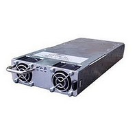
FPSS1U
Description
RACK 3 SLOT FOR FPS1000
Manufacturer
TDK Corporation
Series
FPSr
Specifications of FPSS1U
Accessory Type
Rack System
No. Of Slots
3
Peak Reflow Compatible (260 C)
No
External Width
19.00"
Rack U Height
1
External Depth
13.82"
For Use With
285-1239 - PWR SUP FNT END 48V 1008W 21A285-1238 - PWR SUP FNT END 32V 992W 31A285-1237 - PWR SUP FNT END 24V 960W 40A
Lead Free Status / RoHS Status
Lead free / RoHS Compliant
For Use With/related Products
FPS1000 Series
Lead Free Status / Rohs Status
RoHS Compliant part
Other names
285-1240
Available stocks
Company
Part Number
Manufacturer
Quantity
Price
Company:

Part Number:
FPSS1U
Manufacturer:
TDK-LAMBDA
Quantity:
232
Company:
Part Number:
FPSS1U/P
Manufacturer:
TDK-LAMBDA
Quantity:
232


CHAPTER 17
17.1 GENERAL
This chapter contains instructions for initial inspection, preparation for use and repackaging for shipment.
In some sections in this chapter, where the instructions for the FPS-T1U and the FPS1000 are identical,
a reference to a section describing the FPS1000 will be given.
17.2 PREPARATION FOR USE
Table 10-1 below describes the basic setup procedure. Follow the instructions in Table 17-1 in the sequence
given to prepare the FPS-T1U rack for use.
17.3 INITIAL INSPECTION
Refer to Sec. 3.3 for details.
17.4 FPS-T1U RACK MOUNTING
The FPS-T1U is designed to be mounted in a 19" rack. Use a support bars or surface to provide adequate
support for the rear of the power supply. Secure the FPS-T1U to its location using the front panel using
M6x12 screws via the mounting holes at its front side (Refer to the outline drawings in Chapter 18).
Do not obstruct the air exhaust at the rear panel of the unit.
17.5 LOCATION MOUNTING AND COOLING
The FPS1000 units installed in the FPS-T1U rack are fan cooled. The air intake is at the front panel and
the exhaust is at the rear panel. Upon installation allow cooling air to reach the front panel and allow
minimum 50mm of unrestricted air space at the rear of the unit for the air exhaust.
17.6 AC SOURCE REQUIREMENTS
Refer to Sect 3.6 for details.
17.7 CONNECTING THE LOAD
17.7.1 Load Wiring
Refer to Sec. 3.7.1, 3.7.2 and 3.7.3 for details.
17.7.2 Inductive loads
To prevent damage to the power supply from inductive kickback, a diode should be connected across the
output. The diode voltage and current rating should be greater than the power supply maximum output
voltage and total current rating. Connect the cathode to the positive output and the anode to the negative
output. Where positive load transients such as back EMF from a motor may occur, connect a surge
suppressor across the output to protect the power supply. The breakdown voltage rating of the suppressor
must be approximately 10% higher than the maximum output voltage of the power supply.
Step no Item
1
2
3
4
Table 17-1: Basic setup procedure
Ensure that all connections are securely tightened before applying power. There is a
potential shock hazard when using a power supply with a rated output greater than 40V.
Inspection
Installation
AC source
Load connection
Turn off the AC input power before making or changing any rear panel connection.
FPS-T1U RACK INSTALLATION
Initial physical inspection of the power supply
Installing the power supply.
Wire size selection.
Description
Ensuring adequate ventilation.
AC source requirements
WARNING
41
FPS-T1U Instruction Manual
Section 3.3
Section 10.4
Section 10.5
Section 3.6
Section 10.7
Reference
Related parts for FPSS1U
Image
Part Number
Description
Manufacturer
Datasheet
Request
R

Part Number:
Description:
KIT F-SERIES CLIPS
Manufacturer:
PHIHONG USA
Datasheet:

Part Number:
Description:
TDK DC to DC Converters, DC to AC Inverters
Manufacturer:
TDK Corporation
Datasheet:
Part Number:
Description:
TDK DC to DC Converters, DC to AC Inverters
Manufacturer:
TDK Corporation
Datasheet: