FPSS1U TDK Corporation, FPSS1U Datasheet - Page 35
FPSS1U
Manufacturer Part Number
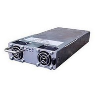
FPSS1U
Description
RACK 3 SLOT FOR FPS1000
Manufacturer
TDK Corporation
Series
FPSr
Specifications of FPSS1U
Accessory Type
Rack System
No. Of Slots
3
Peak Reflow Compatible (260 C)
No
External Width
19.00"
Rack U Height
1
External Depth
13.82"
For Use With
285-1239 - PWR SUP FNT END 48V 1008W 21A285-1238 - PWR SUP FNT END 32V 992W 31A285-1237 - PWR SUP FNT END 24V 960W 40A
Lead Free Status / RoHS Status
Lead free / RoHS Compliant
For Use With/related Products
FPS1000 Series
Lead Free Status / Rohs Status
RoHS Compliant part
Other names
285-1240
Available stocks
Company
Part Number
Manufacturer
Quantity
Price
Company:

Part Number:
FPSS1U
Manufacturer:
TDK-LAMBDA
Quantity:
232
Company:
Part Number:
FPSS1U/P
Manufacturer:
TDK-LAMBDA
Quantity:
232


CHAPTER 12 BASIC CONNECTIONS FOR OPERATION FPS-S1U RACK
12.1 Connecting single load, Local sensing
Local sensing is suitable for applications where load regulation is not critical. Fig 12-1 shows recommended
load and sensing connections for applications with a single load.
*
12.2 Connecting Single Load, Remote Sensing
Remote sensing is used in cases where the load regulation is important at the load terminals. Use twisted
or shielded wires to minimize noise pick-up. If shielded wires are used, the shield should be connected
to the ground at one point, either the power supply side or the load. The optimal point for the shield ground
should be determined by experimentation. Refer to the power supply specifications for the maximum
voltage drop allowed at the load wires.
12.3 Multiple loads connection
If remotely located output distribution terminals are used, the power supply output terminals should be
connected to the distribution terminals by a pair of twisted or shielded wires. Each load should be separately
connected to the remote distribution terminals (see Fig 12-3). If remote sensing is required, the sensing
wires should be connected to the distribution terminals or at the most critical load.
FPS-S1U
SIGNAL
In Local sense applications, the +/- sense have to be connected to the
+/-V terminals of the FPS-S1U prior to operating the FPS1000 units plugged in.
RET
SIGNAL
SIGNAL
FPS-S1U
RET
11
FPS-S1U
RTN
11
11
OFF
ON/
A
OFF
ON/
5
A
5
OFF
ON/
B
OFF
OFF
ON/
ON/
15
A
B
5
15
OFF
ON/
Fig 12-3: Multiple loads connection with distribution terminal
C
OFF
ON/
25
C
OFF
ON/
B
+V
+S
25
-S
-V
15
Fig 12-1: single load connection, local sensing
+V
+S
Fig 12-2: Remote sensing, single load.
-S
-V
OFF
13
22
ON/
C
25
13
22
+V
+S
-S
-V
+V
Sense lines
Twisted pairs
13
22
-V
Load line. Up to 1V drop.
*
Load line.
Up to 1V drop.
32
+V
-V
LOAD
+V
-V
LOAD
+
+
+
-
-
-
LOAD # 1
LOAD # 2
LOAD # 3
Related parts for FPSS1U
Image
Part Number
Description
Manufacturer
Datasheet
Request
R

Part Number:
Description:
KIT F-SERIES CLIPS
Manufacturer:
PHIHONG USA
Datasheet:

Part Number:
Description:
TDK DC to DC Converters, DC to AC Inverters
Manufacturer:
TDK Corporation
Datasheet:
Part Number:
Description:
TDK DC to DC Converters, DC to AC Inverters
Manufacturer:
TDK Corporation
Datasheet: