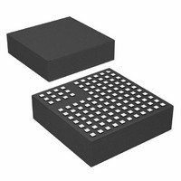
LTM8027IV#PBF Linear Technology, LTM8027IV#PBF Datasheet - Page 11

LTM8027IV#PBF
Manufacturer Part Number
LTM8027IV#PBF
Description
IC BUCK SYNC ADJ 4A 113LGA
Manufacturer
Linear Technology
Series
µModuler
Type
Point of Load (POL) Non-Isolatedr
Datasheet
1.LTM8027MPVPBF.pdf
(22 pages)
Specifications of LTM8027IV#PBF
Design Resources
LTM8027 Spice Model
Output
2.5 ~ 24 V
Number Of Outputs
1
Power (watts)
96W
Mounting Type
Surface Mount
Voltage - Input
4.5 ~ 60 V
Package / Case
113-LGA
1st Output
2.5 ~ 24 VDC @ 4A
Size / Dimension
0.59" L x 0.59" W x 0.17" H (15mm x 15mm x 4.32mm)
Power (watts) - Rated
96W
Operating Temperature
-40°C ~ 125°C
Efficiency
95%
Primary Input Voltage
60V
No. Of Outputs
1
Output Voltage
24V
Output Current
4A
No. Of Pins
113
Operating Temperature Range
-40°C To +125°C
Voltage Regulator Type
Buck DC/DC Converter
Rohs Compliant
Yes
Lead Free Status / RoHS Status
Lead free / RoHS Compliant
3rd Output
-
2nd Output
-
Available stocks
Company
Part Number
Manufacturer
Quantity
Price
APPLICATIONS INFORMATION
For most applications, the design process is straight
forward, summarized as follows:
1. Look at Table 2 and find the row that has the desired
2. Apply the recommended C
3. Connect the BIAS pins as indicated.
While these component and connection combinations have
been tested for proper operation, it is incumbent upon the
user to verify proper operation over the intended system’s
line, load and environmental conditions.
Capacitor Selection Considerations
The C
minimum recommended values for the associated oper-
ating conditions. Applying capacitor values below those
indicated in Table 2 is not recommended, and may result
in undesirable operation. Using larger values is generally
acceptable, and can yield improved dynamic response, if
it is necessary. Again, it is incumbent upon the user to
verify proper operation over the intended system’s line,
load and environmental conditions.
Ceramic capacitors are small, robust and have very low
ESR. However, not all ceramic capacitors are suitable.
X5R and X7R types are stable over temperature and ap-
plied voltage and give dependable service. Other types,
including Y5V and Z5U have very large temperature and
voltage coefficients of capacitance. In an application cir-
cuit they may have only a small fraction of their nominal
capacitance resulting in much higher output voltage ripple
than expected.
A final precaution regarding ceramic capacitors concerns
the maximum input voltage rating of the LTM8027. A
ceramic input capacitor combined with trace or cable
inductance forms a high Q (under damped) tank circuit.
If the LTM8027 circuit is plugged into a live supply, the
input range and output voltage.
IN
and C
OUT
capacitor values in Table 2 are the
IN
, C
OUT
, R
ADJ
and R
T
values.
input voltage can ring to twice its nominal value, possi-
bly exceeding the device’s rating. This situation is easily
avoided; see the Hot-Plugging Safely section.
Input Power Requirements
The LTM8027 is biased using an internal linear regulator
to generate operational voltages from the V
all of the circuitry in the LTM8027 is biased via this internal
linear regulator output (INTV
This pin is internally decoupled with a low ESR capacitor
to GND. The INTV
provided there is ample voltage on the V
regulator has approximately 1V of dropout, and will follow
the V
The LTM8027 has a typical start-up requirement of V
7.5V. This assures that the onboard regulator has ample
headroom to bring the internal regulator (INTV
its UVLO threshold. The INTV
current, so forcing the BIAS1 and BIAS2 pins above 8.5V
allows use of externally derived power for the IC. This
effectively shuts down the internal linear regulator and
reduces power dissipation within the LTM8027. Using
the onboard regulator for start-up, then applying power
to BIAS1 and BIAS2 from the converter output maximizes
conversion efficiencies and is a common practice. If IBIAS1
is maintained above 6.5V using an external source, the
LTM8027 can continue to operate with V
BIAS Power
The internal circuitry of the LTM8027 is powered by the
INTV
tioned internal linear regulator or the BIAS1 pin, if it is
greater than 8.5V. Since the internal linear regulator is by
nature dissipative, deriving INTV
through the BIAS pins reduces the power lost within the
LTM8027 and can increase overall system efficiency.
CC
IN
pin with voltages below the dropout threshold.
bus, which is derived either from the afore men-
CC
regulator generates an 8V output
CC
CC
CC
regulator can only source
on the Block Diagram).
from an external source
LTM8027
IN
IN
pin. The INTV
IN
as low as 4.5V.
pin. Virtually
CC
11
) above
8027fa
IN
CC
>


