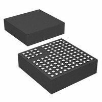
LTM8027IV#PBF Linear Technology, LTM8027IV#PBF Datasheet - Page 10

LTM8027IV#PBF
Manufacturer Part Number
LTM8027IV#PBF
Description
IC BUCK SYNC ADJ 4A 113LGA
Manufacturer
Linear Technology
Series
µModuler
Type
Point of Load (POL) Non-Isolatedr
Datasheet
1.LTM8027MPVPBF.pdf
(22 pages)
Specifications of LTM8027IV#PBF
Design Resources
LTM8027 Spice Model
Output
2.5 ~ 24 V
Number Of Outputs
1
Power (watts)
96W
Mounting Type
Surface Mount
Voltage - Input
4.5 ~ 60 V
Package / Case
113-LGA
1st Output
2.5 ~ 24 VDC @ 4A
Size / Dimension
0.59" L x 0.59" W x 0.17" H (15mm x 15mm x 4.32mm)
Power (watts) - Rated
96W
Operating Temperature
-40°C ~ 125°C
Efficiency
95%
Primary Input Voltage
60V
No. Of Outputs
1
Output Voltage
24V
Output Current
4A
No. Of Pins
113
Operating Temperature Range
-40°C To +125°C
Voltage Regulator Type
Buck DC/DC Converter
Rohs Compliant
Yes
Lead Free Status / RoHS Status
Lead free / RoHS Compliant
3rd Output
-
2nd Output
-
Available stocks
Company
Part Number
Manufacturer
Quantity
Price
LTM8027
BLOCK DIAGRAM
OPERATION
The LTM8027 is a standalone nonisolated step-down
switching DC/DC power supply with an input voltage
range of 4.5V to 60V that can deliver up to 4A of output
current. This module provides a precisely regulated output
voltage up to 24V, programmable via one external resistor.
Given that the LTM8027 is a step-down converter, make
sure that the input voltage is high enough to support the
desired output voltage and load current. A simplified block
diagram is given above. The LTM8027 contains a current
mode controller, power switching element, power induc-
tor, power MOSFETs and a modest amount of input and
output capacitance.
10
V
RUN
SS
SYNC
IN
CONTROLLER
CURRENT
MODE
GND
R
T
V
IN
REGULATOR
INTERNAL
LINEAR
The LTM8027 is a fixed frequency PWM regulator. The
switching frequency is set by simply connecting the ap-
propriate resistor from the RT pin to GND.
A linear regulator provides internal power (shown as
INTV
The bias regulator normally draws power from the V
pin, but if the BIAS1 pin is connected to an external volt-
age higher than 8.5V, bias power will be drawn from the
external source (typically the regulated output voltage).
This improves efficiency. The RUN pin is used to enable
or place the LTM8027 in shutdown, disconnecting the
output and reducing the input current to less than 9µA.
CC
on the Block Diagram) to the control circuitry.
INTV
6.8µH
4.7pF
CC
ADJ
499k
CONNECTION
INTERNAL
TO V
2.2µF
OUT
BIAS1
BIAS2
V
AUX
OUT
8027 BD
8027fa
IN


