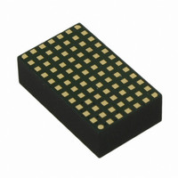
LTM4618IV#PBF Linear Technology, LTM4618IV#PBF Datasheet - Page 3

LTM4618IV#PBF
Manufacturer Part Number
LTM4618IV#PBF
Description
IC DC-DC UMODULE BUCK 6A 84-LGA
Manufacturer
Linear Technology
Series
µModuler
Type
Point of Load (POL) Non-Isolatedr
Datasheet
1.LTM4618EVPBF.pdf
(24 pages)
Specifications of LTM4618IV#PBF
Output
0.8 ~ 5 V
Number Of Outputs
1
Power (watts)
30W
Mounting Type
Surface Mount
Voltage - Input
4.5 ~ 26.5 V
Package / Case
84-LGA
1st Output
0.8 ~ 5 VDC @ 6A
Size / Dimension
0.59" L x 0.35" W x 0.17" H (15mm x 9mm x 4.32mm)
Power (watts) - Rated
30W
Operating Temperature
-40°C ~ 125°C
Lead Free Status / RoHS Status
Lead free / RoHS Compliant
3rd Output
-
2nd Output
-
Available stocks
Company
Part Number
Manufacturer
Quantity
Price
ELECTRICAL CHARACTERISTICS
operating temperature range, otherwise specifi cations are at T
SYMBOL
I
I
INTV
V
VLDO External
V
Output Specifi cations
I
ΔV
ΔV
V
f
ΔV
t
ΔV
t
I
Control Section
V
I
V
I
DF
t
f
f
Q(VIN)
S(VIN)
OUT(DC)
S
START
SETTLE
OUT(PK)
FB
TK/SS
ON(MIN)
NOM
LOW
EXTVCC
EXTVCC
OUT(AC)
FB
OVL
V
MAX
OUT(LINE)
OUT(LOAD)
OUT(START)
OUTLS
V
OUT
CC
OUT
Hysteresis EXTV
PARAMETER
Input Supply Bias Current
Input Supply Current
Internal V
EXTV
EXTV
Output Continuous Current Range
Line Regulation Accuracy
Load Regulation Accuracy
Output Ripple Voltage
Output Ripple Voltage Frequency
Turn-On Overshoot
Turn-On Time
Peak Deviation for Dynamic Load
Settling Time for Dynamic Load Step
Output Current Limit
Error Amplifi er Feedback Voltage
Error Amplifi er Feedback Current
Feedback Voltage Lockout
Soft-Start Charge Current
Maximum Duty Factor
Minimum On-Time
Nominal Frequency
Lowest Frequency
CC
CC
CC
Switchover Voltage
Voltage Drop
Hysteresis
CC
Voltage
CONDITIONS
V
V
Shutdown, RUN = 0, V
V
V
V
EXTV
INTV
V
V
I
V
I
I
C
V
C
V
Load: 0% to 50% of Full Load
C
Load: 0% to 50% of Full Load
C
C
I
(Note 3)
Measured at V
V
In Dropout (Note 3)
(Note 3)
V
V
OUT
OUT
OUT
OUT
IN
IN
IN
IN
IN
IN
OUT
IN
OUT
OUT
OUT
OUT
OUT
OUT
OUT
TK/SS
FREQ
FREQ
V
V
V
V
V
V
V
V
V
V
= 12V, V
= 26.5V, V
= 12V, V
= 26.5V, V
= 12V, V
= 12V, V
= 12V, V
CC
= 0A
= 0A, C
= 2A, V
= 0A, V
IN
IN
IN
IN
IN
IN
IN
IN
IN
IN
The
CC
= 2.5V, V
= 100μF ×3 X5R Ceramic
= 2.5V, I
= 100μF ×3 X5R Ceramic,
= 2.5V, I
= 100μF ×3 X5R Ceramic, V
= 100μF ×3 X5R Ceramic, V
= 100μF ×3 X5R Ceramic
= 1.2V
= 0V
= 0V
= 12V, V
= 26.5V, V
= 12V
= 26.5V
= 12V
= 26.5V
= 12V
= 12V
= 6V, V
= 26.5V, V
= 20mA, V
Ramping Positive
A
l
= 25°C (Note 2), V
OUT
OUT
RUN
OUT
OUT
OUT
IN
OUT
denotes the specifi cations which apply over the full internal
OUT
OUT
OUT
OUT
OUT
FB
IN
= 12V, V
OUT
= 2.5V, I
= 2.5V, I
= 2.5V (Note 4)
= 2.5V, 0 to 6A (Note 4)
= 100μF ×3 X5R Ceramic
= 2.5V
> 2V, No Load
from 6V to 26.5V
OUT
OUT
= 0A
= 0A, TK/SS Capacitor = 0.01μF
= 2.5V, I
= 2.5V, I
EXTVCC
= 2.5V
= 2.5V
= 2.5V
= 2.5V
IN
OUT
OUT
OUT
= 26.5V
= 5V
OUT
OUT
= 2.5V, V
= 0A
= 6A
= 0A
= 6A
IN
OUT
OUT
= 12V, per typical application in Figure 21.
FREQ
= 2.5V
= 2.5V
= INTV
CC
l
l
l
l
0.792
0.788
0.84
MIN
450
210
4.5
0.9
4.8
0
1.430
0.675
0.02
0.75
0.70
0.86
TYP
200
780
–10
500
250
LTM4618
4.7
0.3
0.8
0.8
1.3
26
20
80
50
10
12
20
20
15
10
11
11
97
90
5
0.808
0.808
MAX
0.04
0.88
100
–50
550
290
5.2
0.6
1.7
6
UNITS
4618fa
3
%/V
kHz
kHz
kHz
mA
mA
mV
mV
mV
mV
mV
mV
mV
ms
ms
μA
nA
μA
μs
ns
%
%
A
A
V
V
A
A
A
V
V
V


