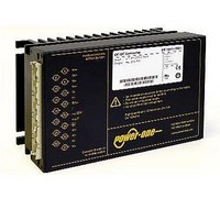
AK1301-7R POWER ONE, AK1301-7R Datasheet - Page 4

AK1301-7R
Manufacturer Part Number
AK1301-7R
Description
CONV INPUT 8-35VDC OUTPUT 12V
Manufacturer
POWER ONE
Series
Kr
Type
Isolatedr
Datasheet
1.AK1301-7R.pdf
(29 pages)
Specifications of AK1301-7R
Output
12V
Number Of Outputs
1
Power (watts)
150W
Mounting Type
Surface Mount
Voltage - Input
8 ~ 35V
Package / Case
Module
1st Output
12 VDC @ 10A
Size / Dimension
6.60" L x 4.40" W x 3.20" H (168mm x 111mm x 80mm)
Power (watts) - Rated
120W
Efficiency
80%
Approvals
CE, cUL, TUV, UL
Output Power
150 W
Input Voltage Range
8 V to 35 V
Input Voltage (nominal)
15 V
Output Voltage (channel 1)
12 V
Output Current (channel 1)
10 A
Package / Case Size
168 mm x 111 mm x 80 mm
Output Type
Isolated
Output Voltage
12 V
Lead Free Status / RoHS Status
Contains lead / RoHS non-compliant
3rd Output
-
2nd Output
-
4th Output
-
Lead Free Status / Rohs Status
Lead free / RoHS Compliant
Other names
Q1792212
Functional Description
The input voltage is fed via an input fuse, an input filter, a
rectifier, and an inrush current limiter to a boost converter.
This step-up converter provides a sinusoidal input current
(IEC/EN 61000-3-2, class D equipment) and charges the
bulk capacitor C
sources a single-transistor forward converter and provides
the power during the hold-up time.
The main transformer exhibits a separate secondary
winding for each output. Each generated voltage is
rectified and smoothed by the power choke and the output
Fig. 1
Block diagram of single-output models
Fig. 2
Block diagram of double-output models
BCD20001-G Rev AC, 16-Dec-2010
1
2
3
1
2
3
Transient suppressor (VDR)
Inrush current limiter (NTC, only models with T
Bulk capacitor C
Transient suppressor (VDR)
Inrush current limiter (NTC, only models with T
Bulk capacitor C
N~
L~
26
28
30
32
24
L~
N~
30
32
24
28
26
b
b
b
; bulk voltage approx. 370 V
; bulk voltage approx. 370 V
to approx. 370 VDC. This capacitor
1
C
C
Y
Y
1
C
C
Y
Y
2
2
A min
A min
= –25 °C ) or option E
= –25 °C ) or option E
C
i
C
3
Page 4 of 29
i
3
+
+
filter. The control logic senses the main output voltage V
or V
admissible output currents, the control signal for the
switching transistor of the forward converter.
The second output of double output models is tracking to
the main output, but has its own current limiting circuit. If
the main output voltage drops due to current limitation, the
second output voltage will fall as well and vice versa.
A separate auxiliary converter generates the supply
voltages for all primary and secondary control circuits and
options.
o1
150 – 280 Watt AC-DC Converters
and generates, with respect to the maximum
C
C
Y
Y
K Series with PFC Data Sheet
C
Y
P
P
– +
03001c
–
03002c
www.power-one.com
+
16
18
20
22
12
4
6
8
10
14
Vo+
Vo–
R
i
T
S–
D/V
S+
16
18
20
22
12
14
4
6
8
10
R
i
D
T
Vo1+
Vo1–
Vo2–
Vo2+
o


