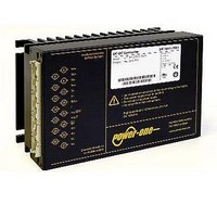
AK1301-7R POWER ONE, AK1301-7R Datasheet - Page 27

AK1301-7R
Manufacturer Part Number
AK1301-7R
Description
CONV INPUT 8-35VDC OUTPUT 12V
Manufacturer
POWER ONE
Series
Kr
Type
Isolatedr
Datasheet
1.AK1301-7R.pdf
(29 pages)
Specifications of AK1301-7R
Output
12V
Number Of Outputs
1
Power (watts)
150W
Mounting Type
Surface Mount
Voltage - Input
8 ~ 35V
Package / Case
Module
1st Output
12 VDC @ 10A
Size / Dimension
6.60" L x 4.40" W x 3.20" H (168mm x 111mm x 80mm)
Power (watts) - Rated
120W
Efficiency
80%
Approvals
CE, cUL, TUV, UL
Output Power
150 W
Input Voltage Range
8 V to 35 V
Input Voltage (nominal)
15 V
Output Voltage (channel 1)
12 V
Output Current (channel 1)
10 A
Package / Case Size
168 mm x 111 mm x 80 mm
Output Type
Isolated
Output Voltage
12 V
Lead Free Status / RoHS Status
Contains lead / RoHS non-compliant
3rd Output
-
2nd Output
-
4th Output
-
Lead Free Status / Rohs Status
Lead free / RoHS Compliant
Other names
Q1792212
After the ACFAIL signal has gone low, the VME standard
requires a hold-up time t
output drops at full load to 4.875 V. This hold-up time t
provided by the capacitance supporting the boost voltage
V
Table 25: Undervoltage monitor functions
Option V operates independently of the built-in input
undervoltage lockout circuit. A logic "low" signal is
generated at pin 20, as soon as one of the monitored
voltages drops below the preselected threshold level V
The return for this signal is S– or Vo1–. The V output
recovers, when the monitored voltage(s) exceed(s) V
The threshold level V
customer-specified value.
V-output (V2, V3):
Connector pin V is internally connected to the open collec-
tor of an NPN transistor. The emitter is connected to S– or
Vo1–. V
voltage level (V
open collector should not exceed 50 mA. The NPN output
is not protected against external overvoltages. V
not exceed 60 V.
Table 26: Status of V output
Fig. 42
Output configuration of options V2 and V3
(VME compatible)
BCD20001-G Rev AC, 16-Dec-2010
1
2
b
. See Hold-up Time.
Option V monitors V
trigger level is adjusted in the factory to 355 VDC.
Fixed value between 95% and 98.5% of V
V
V output
b
and V
V
V2
V3
V
V
b
b
or V
, V
o1
0.6 V (logic low) corresponds to a monitored
o
o
status
V
i
V
and/or V
t
+ V
t
Monitoring
yes
yes
V
NPN open
collector
h
b
b
generated by the boost regulator. The
to
h
o
is adjusted in the factory to a
yes
of at least 4 ms before the 5.1 V
) V
no
V
high, H, I
o1
low, L, V
t
. The current I
range of threshold level
355 VDC
355 VDC
11009a
Minimum adjustment
V
V
V
t b
V output, V
14
20
0.6 V at I
25 µA at V
Vo+
V
S–
1
1
o1
0.95
I
V
V
V
V
–
through the
V
V
V
0.985 V
V
= 50 mA
–
to
R
V
= 5.1 V
p
should
t
+ V
Page 27 of 29
h
o1
is
h
2
t
.
.
K Connector H15S4
Models with 5.1 V output are fitted with a connector H15S4
(rather than H15S2). This option should be used for new
designs and provides compatibility to LK1001 models.
B, B1, B2 Cooling Plate
Where a cooling surface is available, we recommend the
use of a cooling plate instead of the standard heat sink.
The mounting system should ensure sufficient cooling
capacity to guarantee that the maximum case tempera-
ture T
lated by:
For the dimensions of the cooling plates, see Mechnical
Data. Option B2 is for customer-specific models with
elongated case (for 220 mm DIN-rack depth).
G RoHS
Models with G as last character of the type designation are
RoHS-compliant for all six substances.
Efficiency
P
C max
Loss
150 – 280 Watt AC-DC Converters
= –––––––––– • V
is not exceeded. The cooling capacity is calcu-
(100% –
see Model Selection
K Series with PFC Data Sheet
o
• I
o
www.power-one.com


