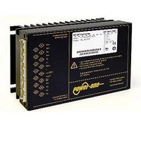
AK1301-7R POWER ONE, AK1301-7R Datasheet - Page 16

AK1301-7R
Manufacturer Part Number
AK1301-7R
Description
CONV INPUT 8-35VDC OUTPUT 12V
Manufacturer
POWER ONE
Series
Kr
Type
Isolatedr
Datasheet
1.AK1301-7R.pdf
(29 pages)
Specifications of AK1301-7R
Output
12V
Number Of Outputs
1
Power (watts)
150W
Mounting Type
Surface Mount
Voltage - Input
8 ~ 35V
Package / Case
Module
1st Output
12 VDC @ 10A
Size / Dimension
6.60" L x 4.40" W x 3.20" H (168mm x 111mm x 80mm)
Power (watts) - Rated
120W
Efficiency
80%
Approvals
CE, cUL, TUV, UL
Output Power
150 W
Input Voltage Range
8 V to 35 V
Input Voltage (nominal)
15 V
Output Voltage (channel 1)
12 V
Output Current (channel 1)
10 A
Package / Case Size
168 mm x 111 mm x 80 mm
Output Type
Isolated
Output Voltage
12 V
Lead Free Status / RoHS Status
Contains lead / RoHS non-compliant
3rd Output
-
2nd Output
-
4th Output
-
Lead Free Status / Rohs Status
Lead free / RoHS Compliant
Other names
Q1792212
Fig. 26a
Conducted emissions (peak) at the phase input according
to EN 55011/22, measured at V
The neutral line performs quite similar.
BCD20001-G Rev AC, 16-Dec-2010
10
Table 11: Electromagnetic immunity (type tests)
Emissions
70
50
30
Electromagnetic Compatibility (EMC)
A metal oxide VDR together with an input fuse and an input
filter form an effective protection against high input
Immunity
dbµV
Phenomenon
Electrostatic
discharge
(to case)
Electromagnetic IEC/ EN
field
Electrical fast
transients/burst 61000-4-4
Surges
Conducted
disturbances
Voltage dips,
short interrup-
tions and
variations
1
2
3
4
i = input, o = output, c = case
A = Normal operation, no deviation from specifications, B = Normal operation, temporary loss of function or deviation from
specs possible
For converters with version V102 or higher. Older LKP models meet only B.
Only LKP models have been tested.
0.2
LK4301-6, Peak L, conducted, 0.15 - 30 MHz, PMM 8000, 30-May-06
0.5
Standard Level
IEC/ EN
61000-4-2
61000-4-3
IEC/ EN
IEC/ EN
61000 -4-5
IEC / EN
61000-4-6
IEC/ EN
6100-4-11
1
2
40%
0%
i nom
4
3
3
3
3
and I
contact discharge
i, o, signal wires
capacitive, o/c
air discharge
5
Coupling
o nom
±i/c, +i/–i
mode
antenna
direct
+i/–i
+i/–i
+i/–i
±i/c
(LK4301-7R).
10
EN 55022 B
1
20
(140 dB V)
Page 16 of 29
15000 V
±2000 V
±2000 V
230
applied
8000 V
10 VAC
230
MHz
10 V/m
10 V/m
Value
230
230
9 2
0
p
p
p
p
Fig. 26b
Conducted emissions (peak) at the phase input according
to EN 55011/22, measured at V
7R). The neutral line performs quite similar.
transient
installations. The converters have been successfully
tested to the following specifications:
dbµV
70
50
30
10
50% duty cycle,
200 Hz repetition
bursts of 5/50 ns
period: 300 ms
2.5/5 kHz over
15 ms; burst
Waveform
2
frequency
1.2/50 µs
AM 80%
AM 80%
0.2
1/50 ns
1 kHz
1 kHz
150 – 280 Watt AC-DC Converters
1
LKP5660-6, Peak L, conducted, 0.15 - 30 MHz, PMM 8000, 30-May-06
2 s
voltages,
K Series with PFC Data Sheet
0.5
Source
imped.
150 pF
330
150
50
12
n.a.
2
n.a.
n.a.
1
which
5 pos. and 5 neg.
10 positive and
80 – 1000 MHz
coupling mode
coupling mode
0.15 – 80 MHz
60 s negative
transients per
60 s positive
pulse modul.
procedure
10 negative
900 ±5 MHz
2
discharges
surges per
sine wafe
i nom
typically
Test
and I
5
o nom
www.power-one.com
occur
(LKP5660-
oper. crit.
yes
yes
yes
yes
yes
yes
10
yes
In
EN 55022 B
in
Perf.
20
A
B
B
A
A
A
A
A
4
4
3
most
MHz
2


