GW5BNC15L02 Sharp Microelectronics, GW5BNC15L02 Datasheet - Page 7
GW5BNC15L02
Manufacturer Part Number
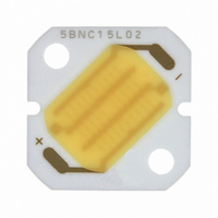
GW5BNC15L02
Description
LED MOD 3.5WATT ZENIGATA 5000K
Manufacturer
Sharp Microelectronics
Type
Without Connectorr
Specifications of GW5BNC15L02
Color
White
Luminous Flux @ Current - Test
190 lm
Current - Test
360mA
Current - Max
360mA
Driver Circuitry
No
Voltage
10.2V
Wavelength
5000K
Configuration
Single
With Connector
No
Voltage - Input
10.2V
Power - Input
3.5W
Illumination Color
White
Wavelength/color Temperature
5000 K
Luminous Flux
190 lm
Power Rating
4.4 W
Operating Voltage
10.2 V
Operating Current
400 mA
Minimum Operating Temperature
- 30 C
Maximum Operating Temperature
+ 90 C
Lens Shape
Rectangular
Number Of Leds
1
Lead Free Status / RoHS Status
Lead free / RoHS Compliant
Interface
-
Lead Free Status / Rohs Status
Lead free / RoHS Compliant
Other names
425-2733
GW5BNC15L00
GW5BNC15L00


■ Design Considerations
1. This product is not designed to be electromagnetic- and ionized-particle-radiation resistant.
2. Always use an adequate heatsink with this part, in combination with either (or both) a thermally conductive sheet
3. Do not allow the circuit design to apply any reverse voltage to the LEDs.
4. This module requires a constant-current source for its drive. A constant-voltage supply may provide more than
5. If current in excess of the rated maximum are supplied to this part, hazardous conditions may be created, including
6. If the lead wire to the part comes loose, it could contact the case or heatsink, thereby creating a short circuit and pos-
■ Manufacturing Guidelines
1. Sharp does not recommend cleaning this part, as the silicone resin may be corroded by solvents.
1. Sharp recommends soldering by hand, with a thermally-controlled iron at 380°C; within 10 seconds for each
2. When soldering, do not touch the tip of the iron to the yellow phosphor.
3. This product is not designed for solder reflow or solder flow methods.
4. Do not subject the package to excessive mechanical force during soldering as it may cause deformation or
1. Sharp recommends taking particular notice of the installation method, as the mounting board’s material is alumi-
2. Use screws, adhesives, or both when mounting this device to its heatsink. When using only adhesives, be sure
3. When screw mounting:
Design Guidelines
Cleaning Instructions
Soldering Instructions
Mechanical Installation Instructions
or heat-conducting grease.
the rated current due to lowered V
excess heating, smoke emission, or a possible fire. Take appropriate measures to control excess current and voltage.
sible shock hazard. Take appropriate measures to prevent the lead wire from coming into contact with other parts.
place. Solder on a surface that does not conduct heat.
defects in plated connections. Internal connections may be severed due to mechanical force placed on the pack-
age due to the PCB flexing during the soldering process.
nized ceramic. If incorrectly installed, problems with non-radiation may occur due to cracking of the mounting board.
to check their effectiveness. Use thread locking materials to prevent screws from loosening due to thermal
cycling. If the part is separated from its heatsink, a catastrophic temperature rise may occur, causing self-des-
oldering, device deterioration if not destruction, and smoke emission.
• Refer to Fig. 11 for the recommended dimensions.
• Screw torque: within 0.2 N•m.
• Use thread locking materials.
• Use materials with low galvanic action, such as stainless steel.
• Do not use flathead screws, which can cause substrate cracks due to stress at the screw holes.
• Do not install the part into a board which is warped in a convex direction. This part can be easily damaged by
• To maximize thermal efficiency between the device and its heatsink, Sharp recommends a thermally-conduc-
• Circuit board cracks can be caused when screws are tightened; be sure to check the actual conditions carefully.
torquing it to a convexedly-warped mounting surface.
tive sheet and conductive grease.
F
created caused by part heating.
7
GW5xxC15Lx2
Sheet No.: DG-xxxxx
Related parts for GW5BNC15L02
Image
Part Number
Description
Manufacturer
Datasheet
Request
R

Part Number:
Description:
IC FLASH 32MBIT 110NS 56SSOP
Manufacturer:
Sharp Microelectronics
Datasheet:

Part Number:
Description:
IC FLASH 16MBIT 100NS 56TSOP
Manufacturer:
Sharp Microelectronics
Datasheet:

Part Number:
Description:
IC FLASH 64MBIT 120NS 56TSOP
Manufacturer:
Sharp Microelectronics
Datasheet:

Part Number:
Description:
IC FLASH 16MBIT 90NS 48TSOP
Manufacturer:
Sharp Microelectronics
Datasheet:
Part Number:
Description:
IC SRAM 16KBIT 100NS 24DIP
Manufacturer:
Sharp Microelectronics
Datasheet:
Part Number:
Description:
IC SRAM 16KBIT 100NS 24SOP
Manufacturer:
Sharp Microelectronics
Datasheet:
Part Number:
Description:
IC SRAM 64KBIT 100NS 28DIP
Manufacturer:
Sharp Microelectronics
Datasheet:
Part Number:
Description:
IC SRAM 64KBIT 100NS 28SOP
Manufacturer:
Sharp Microelectronics
Datasheet:
Part Number:
Description:
IC SRAM 64KBIT 100NS 28SOP
Manufacturer:
Sharp Microelectronics
Datasheet:
Part Number:
Description:
IC SRAM 256KBIT 70NS 28DIP
Manufacturer:
Sharp Microelectronics
Datasheet:
Part Number:
Description:
IC FLASH 8MBIT 90NS 48TSOP
Manufacturer:
Sharp Microelectronics
Datasheet:
Part Number:
Description:
IC FLASH 8MBIT 85NS 40TSOP
Manufacturer:
Sharp Microelectronics
Datasheet:
Part Number:
Description:
IC FLASH 8MBIT 85NS 40TSOP
Manufacturer:
Sharp Microelectronics
Datasheet:
Part Number:
Description:
IC FLASH 16MBIT 90NS 48TSOP
Manufacturer:
Sharp Microelectronics
Datasheet:
Part Number:
Description:
IC FLASH 16MBIT 70NS 56TSOP
Manufacturer:
Sharp Microelectronics
Datasheet: