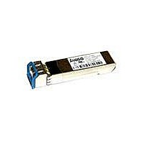
AFCT-701SDZ Avago Technologies US Inc., AFCT-701SDZ Datasheet - Page 10

AFCT-701SDZ
Manufacturer Part Number
AFCT-701SDZ
Description
TXRX SFP+ SMF 10BGD 1310NM
Manufacturer
Avago Technologies US Inc.
Series
-r
Datasheet
1.AFCT-701SDZ.pdf
(18 pages)
Specifications of AFCT-701SDZ
Data Rate
10.312Gbd
Wavelength
1310nm
Applications
Ethernet
Voltage - Supply
3.135 V ~ 3.465 V
Connector Type
LC Duplex
Mounting Type
SFP
For Use With Fiber Type
Multimode
Function
SFP+ 10 Gb ethernet transceiver
Maximum Forward Current
289 mA
Maximum Power Dissipation
1000 mW
Transmission Distance
10 Km
Product
Transceiver
Diode Capacitance
14 pF
Maximum Rise Time
28 ps
Maximum Fall Time
28 ps
Maximum Output Current
20 mA
Operating Supply Voltage
3.465 V
Maximum Operating Temperature
+ 70 C
Minimum Operating Temperature
0 C
Supply Voltage
3.3V
Wavelength Typ
1310nm
Leaded Process Compatible
Yes
Peak Reflow Compatible (260 C)
Yes
Rohs Compliant
No
Lead Free Status / RoHS Status
Contains lead / RoHS non-compliant
For Use With
Multimode Glass
Lead Free Status / RoHS Status
Lead free / RoHS Compliant, Contains lead / RoHS non-compliant
Available stocks
Company
Part Number
Manufacturer
Quantity
Price
Company:
Part Number:
AFCT-701SDZ
Manufacturer:
Avago Technologies
Quantity:
135
Table 5. Low Speed Signal Electrical Characteristics
The following characteristics are defined over the Recommended Operating Conditions unless otherwise noted.
Typical values are for Tc = 40°C. VccT and VccR = 3.3 V.
Parameter
Module Supply Current
Power Dissipation
TX_FAULT, RX_LOS
TX_DISABLE
Notes:
1. Supply current includes both VccT and VccR connections.
2. Measured with a 4.7 k Ω load to VccHost.
3. TX_DISABLE has an internal 4.7 kΩ to 10 kΩ pull-up to VccT
Table 6. High Speed Signal Electrical Characteristics
The following characteristics are defined over the Recommended Operating Conditions unless otherwise noted.
Parameter
Tx Input Differential Voltage, |(TD +) - (TD-)|
Tx Input AC Common Mode Voltage Tolerance
Tx Input Differential S-parameter (100 Ω Ref.)
Tx Input Reflected Differential to
Common Mode Conversion (25 Ω Ref.)
Rx Output Differential Voltage, |(RD +) - (RD-)|
Rx Output Termination Mismatch @ 1MHz
Rx Output AC Common Mode Voltage
Rx Output Output Rise and Fall Time
(20% to 80%)
Rx Output Total Jitter
Rx Output Deterministic Jitter
Rx Output Differential S-parameter
(100 Ω Ref.)
Rx Output Common Mode Reflection
Coefficient (25 Ω Ref.)
Receiver Output Eye Mask
N otes:
1. Internally AC coupled and terminated (100 Ohm differential).
2. Internally AC coupled but requires an external load termination (100 Ohm differential).
3. Reflection Coefficient given by equation SDD11(dB)=Max(-12 + 2*SQRT(f ) -6.3+13Log10(f/5.5)), with f in GHz.
4. Differential Output S-parameter given by equation SDD22(dB)= Max(-12 + 2*SQRT(f ) -6.3+13Log10(f/5.5)), with f in GHz.
5. The RMS value is measured by calculating the standard deviation of the histogram for one UI of the common mode signal.
10
Symbol
I
P
I
V
V
V
CC
OH
Symbol
V
SDD11
SCD11
Vo
DZ
tr, tf
TJ
DJ
SDD22
SCC22
DISS
OL
IH
IL
I
m
Minimum
180
300
28
Minimum
- 50
-
2.0
-0.3
0.3
Typical
Typical
258
850
Maximum
700
15
-12
Note 3
-10
850
5
7.5
0.70
0.42
-12
Note 4
-6
-3
Maximum
289
1000
+ 37.5
0.4
VccT + 0.3
0.8
Unit
mV
mV(RMS)
dB
dB
dB
mV
%
mV(RMS)
ps
Ulp-p
Ulp-p
dB
dB
dB
dB
Notes
Note 1
0.01-1.0 GHz
1.0-11.1 GHz
0.01-11.1 GHz
Note 2
Note 5
0.01-1.0 GHz
1.0-11.1 GHz
0.01-2.5 GHz
2.5-11.1 GHz
See Figure 5a
Unit
mA
mW
mA
V
V
V
Notes
Note 1
Note 2
Note 3


