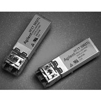
AFCT-5961ATGZ Avago Technologies US Inc., AFCT-5961ATGZ Datasheet - Page 10

AFCT-5961ATGZ
Manufacturer Part Number
AFCT-5961ATGZ
Description
TXRX OPT SM SONET OC3/SDH 2X5
Manufacturer
Avago Technologies US Inc.
Series
METRAKr
Datasheet
1.AFCT-5961TGZ.pdf
(16 pages)
Specifications of AFCT-5961ATGZ
Applications
General Purpose
Data Rate
155Mbps
Wavelength
1300nm
Voltage - Supply
3.1 V ~ 3.5 V
Connector Type
LC Duplex
Mounting Type
Through Hole
Data Rate Max
0.155Gbps
Supply Voltage
3.3V
Wavelength Typ
1300nm
Leaded Process Compatible
Yes
Optical Fiber Type
TX/RX
Data Transfer Rate
155Mbps
Optical Rise Time
2/2.2ns
Optical Fall Time
2/2.2ns
Operating Temperature Classification
Industrial
Peak Wavelength
1360nm
Package Type
DIP With Connector
Operating Supply Voltage (min)
3.1V
Operating Supply Voltage (typ)
3.3V
Operating Supply Voltage (max)
3.5V
Output Current
50mA
Operating Temp Range
-40C to 85C
Mounting
Snap Fit To Panel
Pin Count
10
Lead Free Status / RoHS Status
Lead free / RoHS Compliant
Lead Free Status / RoHS Status
Lead free / RoHS Compliant, Lead free / RoHS Compliant
Process plug
This transceiver is supplied with a process plug for
protection of the optical port within the LC connector
receptacle. This process plug prevents contamina-
tion during wave solder and aqueous rinse as well as
during handling, shipping and storage. It is made of a
high-temperature, molded sealing material that can
withstand +85 °C, and a rinse pressure of 110 lbs per
square inch.
The process plug should only be used once. After
removing it from the transceiver, it must not be used
again as a process plug; however, if it has not been con-
taminated it can be reused as a dust cover.
Recommended Solder fluxes
Solder fluxes used with the AFCT-5961TLZ/TGZ/ATLZ/
ATGZ/NLZ/NGZ should be water-soluble, organic fluxes.
Recommended solder fluxes include Lonco 3355-11
from London Chemical West, Inc. of Burbank, CA, and
100 Flux from Alpha-Metals of Jersey City, NJ.
Figure 8. Recommended Panel Mounting
10
(0.4 ±0.004)
DIMENSIONS IN MILLIMETERS (INCHES)
1.
2.
10.16 ±0.1
FIGURE DESCRIBES THE RECOMMENDED FRONT PANEL OPENING FOR A LC OR SG SFF TRANSCEIVER.
SFF TRANSCEIVER PLACED AT 15.24 mm (0.6) MIN. SPACING.
(0.56 ±0.004)
14.22 ±0.1
15.24
DETAIL A
(0.6)
TOP OF PCB
15.24
(0.6)
B
(0.039)
(0.62 MAX. 0.59 MIN.)
15.75 MAX. 15.0 MIN.
1
A
SECTION B - B
SOLDER POSTS
Recommended Cleaning/Degreasing Chemicals
Alcohols: methyl, isopropyl, isobutyl.
Aliphatics: hexane, heptane
Other: naphtha.
Do not use partially halogenated hydrocarbons such as
1,1.1 trichloroethane, ketones such as MEK, acetone,
chloroform, ethyl acetate, methylene dichloride, phenol,
methylene chloride, or N-methylpyrolldone. Also, Avago
Technologies does not recommend the use of cleaners
that use halogenated hydrocarbons because of their
potential environmental harm.
LC SFF Cleaning Recommendations
In the event of contamination of the optical ports, the
recommended cleaning process is the use of forced
nitrogen. If contamination is thought to have remained,
the optical ports can be cleaned using a NTT interna-
tional Cletop stick type (diam. 1.25 mm) and HFE7100
cleaning fluid.
B


