AFBR-5905Z Avago Technologies US Inc., AFBR-5905Z Datasheet - Page 9
AFBR-5905Z
Manufacturer Part Number
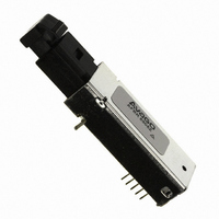
AFBR-5905Z
Description
TXRX OPT OC3 MTRJ SFF 2X5DIP
Manufacturer
Avago Technologies US Inc.
Datasheet
1.AFBR-5905Z.pdf
(13 pages)
Specifications of AFBR-5905Z
Applications
General Purpose
Wavelength
1300nm
Voltage - Supply
3.3V
Connector Type
MTRJ
Mounting Type
Through Hole
Data Rate Max
0.1Gbps
Supply Voltage
3.3V
Wavelength Typ
1308nm
Leaded Process Compatible
Yes
Lead Free Status / RoHS Status
Lead free / RoHS Compliant
Data Rate
-
Lead Free Status / RoHS Status
Lead free / RoHS Compliant, Lead free / RoHS Compliant
Other names
516-1994


Regulatory Compliance
These transceiver products are intended to enable com-
mercial system designers to develop equipment that com-
plies with the various international regulations governing
certification of Information Technology Equipment. See
the Regulatory Compliance Table for details. Additional
information is available from your Avago sales represen-
tative.
Electrostatic Discharge (ESD)
There are two design cases in which immunity to ESD
damage is important. The first case is during handling of
the transceiver prior to mounting it on the circuit board. It
is important to use normal ESD handling precautions for
ESD sensitive devices. These pre-cautions include using
grounded wrist straps, work benches, and floor mats in
ESD controlled areas. The second case to consider is static
discharges to the exterior of the equipment chassis con-
taining the transceiver parts. To the extent that the MT-
RJ connector is exposed to the outside of the equipment
chassis it may be subject to whatever ESD system level
test criteria that the equipment is intended to meet.
9
Regulatory Compliance
These transceiver products are
intended to enable commercial
system designers to develop
equipment that complies with
the various international
regulations governing certifica-
tion of Information Technology
Equipment. See the Regulatory
Compliance Table for details.
Additional information is
available from your Agilent
sales representative.
Electrostatic Discharge (ESD)
There are two design cases in
which immunity to ESD
damage is important.
The first case is during
handling of the transceiver
prior to mounting it on the
circuit board. It is important
to use normal ESD handling
precautions for ESD sensitive
devices. These pre-cautions
include using grounded wrist
straps, work benches, and floor
mats in ESD controlled areas.
Regulatory Compliance Table
9
Feature
Electrostatic Discharge
(ESD) to the Electrical Pins
Electrostatic Discharge
(ESD) to the MT-RJ Receptacle
Electromagnetic
Interference (EMI)
Immunity
Eye Safety
MIL-STD-883C
IEC 801-2
FCC Class B
CENELEC CEN55022 VCCI
Class 2
EN60825-1 (+A11)
Test Method
Variation of
Variation of IEC 61000-4-3
AEL Class 1
The second case to consider is
static discharges to the
exterior of the equipment
chassis containing the
transceiver parts. To the
extent that the MT-RJ
connector is exposed to the
outside of the equipment
chassis it may be subject to
whatever ESD system level test
criteria that the equipment is
intended to meet.
Transceiver Reliability and
Performance Qualification Data
The 2 x 5 transceivers have
passed Agilent reliability and
performance qualification
testing and are undergoing
ongoing quality and reliability
monitoring. Details are avail-
able from your Agilent sales
representative.
Applications Support Materials
Contact your local Agilent
Component Field Sales Office
for information on how to
obtain evaluation boards for
the 2 x 5 transceivers.
Performance
Meets Class 2 (2000 to 3999 Volts).
Connector Receptacle is contacted by a Human Body Model probe.
be noted that final margin depends on the customer's board and chassis
design.
chassis enclosure.
Compliant per Agilent testing under single fault conditions.
Withstand up to 2200 V applied between electrical pins.
Typically withstand at least 25 kV without damage when the MT-RJ
Typically provide a 10 dB margin to the noted standards, however, it should
Typically show no measurable effect from a 10 V/m field swept from 10 to
450 MHz applied to the transceiver when mounted to a circuit card without a
TUV Certification: LED Class 1
Transceiver Reliability and Performance Qualification Data
The 2 x 5 transceivers have passed Avago reliability and
performance qualification testing and are undergoing on-
going quality and reliability monitoring. Details are avail-
able from your Avago sales representative.
Applications Support Materials
Contact your local Avago Component Field Sales Office
for information on how to obtain evaluation boards for
the 2 x 5 transceivers.
Electromagnetic Interference (EMI)
Most equipment designs utilizing this high speed trans-
ceiver from Avago will be required to meet the require-
ments of FCC in the United States, CENELEC EN55022
(CISPR 22) in Europe and VCCI in Japan. This product is
suitable for use in designs ranging from a desktop com-
puter with a single transceiver to a concentrator or switch
product with a large number of transceivers.
Immunity
Equipment utilizing these transceivers will be subject to
radio-frequency electromagnetic fields in some environ-
ments. These transceivers have a high immunity to such
fields.
Electromagnetic Interference (EMI)
Most equipment designs
utilizing this high speed trans-
ceiver from Agilent will be
required to meet the require-
ments of FCC in the United
States, CENELEC EN55022
(CISPR 22) in Europe and
VCCI in Japan.
This product is suitable for
use in designs ranging from a
desktop computer with a single
transceiver to a concentrator
or switch product with a large
number of transceivers.
Immunity
Equipment utilizing these
transceivers will be subject to
radio-frequency
electromagnetic fields in some
environments. These
transceivers have a high
immunity to such fields.
Related parts for AFBR-5905Z
Image
Part Number
Description
Manufacturer
Datasheet
Request
R

Part Number:
Description:
650nm FE Transceiver Eval Kit
Manufacturer:
Avago Technologies US Inc.
Datasheet:

Part Number:
Description:
TXRX ETHERNET 125MBD MMF 2X5
Manufacturer:
Avago Technologies US Inc.
Datasheet:

Part Number:
Description:
TXRX OPT SFP DGTL 850NM IND
Manufacturer:
Avago Technologies US Inc.
Datasheet:

Part Number:
Description:
TXRX OPT SFF 4/2/1GBD 2X7
Manufacturer:
Avago Technologies US Inc.
Datasheet:

Part Number:
Description:
TXRX OPT SFP 4/2/1GBD 850NM
Manufacturer:
Avago Technologies US Inc.
Datasheet:

Part Number:
Description:
TXRX OPT XFP 10GB/S 850NM
Manufacturer:
Avago Technologies US Inc.
Datasheet:

Part Number:
Description:
TXRX OPT 1X9 100MBPS ST EXT TEMP
Manufacturer:
Avago Technologies US Inc.
Datasheet:

Part Number:
Description:
TXRX OPT 1X9 100MBPS SC EXT TEMP
Manufacturer:
Avago Technologies US Inc.
Datasheet:

Part Number:
Description:
TXRX OPT 1X9 100MBPS DUPLEX SC
Manufacturer:
Avago Technologies US Inc.
Datasheet:

Part Number:
Description:
TXRX OPT 1X9 100MBPS DUPLEX ST
Manufacturer:
Avago Technologies US Inc.
Datasheet:

Part Number:
Description:
OPTOCOUPLER GATE DRV 2A 16-SOIC
Manufacturer:
Avago Technologies US Inc.
Datasheet:
Part Number:
Description:
OPTOCOUPLER 2CH 2.5A 16-SOIC
Manufacturer:
Avago Technologies US Inc.
Datasheet:

Part Number:
Description:
OPTOCOUPLER GATE DRV 0.4A 16SOIC
Manufacturer:
Avago Technologies US Inc.
Datasheet:

Part Number:
Description:
OPTOCOUPLER 2.0A 250KHZ 8-DIP
Manufacturer:
Avago Technologies US Inc.
Datasheet:

Part Number:
Description:
OPTOCOUPLER 2.0A 250KHZ GW 8-SMD
Manufacturer:
Avago Technologies US Inc.
Datasheet: