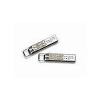
AFBR-57J5APZ Avago Technologies US Inc., AFBR-57J5APZ Datasheet
AFBR-57J5APZ
Specifications of AFBR-57J5APZ


Related parts for AFBR-57J5APZ


AFBR-57J5APZ Summary of contents
Page 1
... SFF-8472 for mechanical and electrical specifi- cations and FOCIS/IEC specifications for optical duplex LC connectors enhancement to the conventional SFP interfaced defined in INF-8074, the AFBR-57J5APZ is compliant to SFF-8472 (Digital Diagnostic Interface for Optical Trans- ceivers). Using the 2-wire serial interface defined in SFF- 8472, the transceiver provides real time temperature, supply voltage, laser bias current, laser average output power and received input power ...
Page 2
... A2, byte 110, bit 2). Eye Safety Circuit The AFBR-57J5APZ provides Class 1 (single fault tolerant) eye safety by design and has been tested for compliance with the requirements listed in Table 1. The eye safety circuit continuously monitors the optical output power ...
Page 3
... It may also result in improper operation and possibly overstress the laser source. Performance deg- radation or device failure may result. Connection of the AFBR-57J5APZ to a light source not compliant with these specifications, operating above maximum operating conditions manner inconsistent with it’s design and function may result in exposure to hazardous light ...
Page 4
... Flammability The AFBR-57J5APZ optical transceiver is made of metal and high strength, heat resistant, chemical resistant and UL 94V-0 flame retardant plastic. Predictive Failure Identification The AFBR-57J5APZ predictive failure feature allows a host to identify potential link problems before system perfor- mance is impacted. Prior identification of link problems enables a host to service an application via “ ...
Page 5
Tx_DISABLE Tx_FAULT SERDES IC PROTOCOL IC LOSS OF SIGNAL 4 kΩ MODULE DETECT SCL SDA Figure 2. Typical Application Configuration 0.1 µ 0.1 µF 10 µF SFP MODULE HOST BOARD NOTE: ...
Page 6
Table 2. Pin Description Pin Name Function/Description 1 VeeT Transmitter Ground 2 TX_FAULT Transmitter Fault Indication – High indicates a fault condition 3 TX_DISABLE Transmitter Disable – Module optical output disables on high or open 4 MOD-DEF2 Module Definition 2 ...
Page 7
Table 3. Absolute Maximum Ratings Parameter Storage Temperature Case Operating Temperature Relative Humidity Supply Voltage Low Speed Input Voltage Notes 1. Absolute Maximum Ratings are those values beyond which damage to the device may occur if these limits are exceeded ...
Page 8
Table 6. Transmitter Optical Characteristics(TC = -40°C to 85°C, VccT, VccR = 3.3V ± 10%) Parameter Modulated Optical Output Power (OMA) (Peak-to-Peak) Average Optical Output Power Center Wavelength Spectral Width – rms Optical Rise/Fall Time RIN 12 (OMA) Transmitter Contributed ...
Page 9
Table 8. Transmitter and Receiver Electrical Characteristics (TC = -40°C to 85°C, VccT, VccR = 3.3V ± 10%) Parameter High Speed Data Input: Transmitter Differential Input Voltage (TD +/-) High Speed Data Output: Receiver Differential Output Voltage (RD +/-) Receiver ...
Page 10
Table 9. Transceiver SOFT DIAGNOSTIC Timing Characteristics (TC = -40°C to 85°C, VccT, VccR = 3.3V ± 10%) Parameter Hardware TX_DISABLE Assert Time Hardware TX_DISABLE Negate Time Time to initialize, including reset of TX_FAULT Hardware TX_FAULT Assert Time Hardware TX_DISABLE ...
Page 11
... IC and laser optical subassembly. Variations in average optical power are not expected under normal operation because the AFBR-57J5APZ uses a closed loop laser bias feedback circuit to maintain constant optical power. This circuit compensates for normal VCSEL parametric variations due to changing transceiver operating points ...
Page 12
V > 3.15V CC TX_FAULT TX_DISABLE TRANSMITTED SIGNAL t_init t-init: TX DISABLE NEGATED V > 3.15V CC TX_FAULT TX_DISABLE TRANSMITTED SIGNAL t_init INSERTION t-init: TX DISABLE NEGATED, MODULE HOT PLUGGED OCCURANCE OF FAULT TX_FAULT TX_DISABLE TRANSMITTED SIGNAL t_fault t-fault: TX ...
Page 13
... Addresses 63 and 95 are checksums calculated (per SFF-8472 and SFF-8074) and stored prior to product shipment. 4. Addresses 68-83 specify the AFBR-57J5APZ ASCII serial number and will vary on a per unit basis. 5. Addresses 84-91 specify the AFBR-57J5APZ ASCII date code and will vary on a per date code basis. 13 ...
Page 14
... Transmitted average optical power (Tx Pwr) is decoded bit unsigned integer in increments of 0.1 uW. 5. Received average optical power (Rx Pwr) is decoded bit unsigned integer in increments of 0.1 uW. 6. Bytes 55-94 are not intended for use with AFBR-57J5APZ, but have been set to default values per SFF-8472. 7. Byte checksum calculated (per SFF-8472) and stored prior to product shipment. ...
Page 15
... Ready) Notes: 1. The response time for soft commands of the AFBR-57J5APZ is 100 msec as specified by the MSA SFF-8472 2. Bit 6 is logic OR’d with the SFP TX_DISABLE input pin 3 ... either asserted will disable the SFP transmitter. Table 15. EEPROM Serial ID Memory Contents – Alarms and Warnings (Address A2h, Bytes 112, 113, 116, 117) ...
Page 16
Figure 5. Module drawing 16 ...
Page 17
X Y 16.25 MIN. PITCH B PCB EDGE 5.68 8.58 11.08 16.25 14.25 REF . 2.0 11x 3 3.2 PIN 1 10.93 9.6 0.8 TYP . 1.55 ± 0.05 ∅ 0 DETAIL ...
Page 18
MAX. 11.73 REF 9.8 MAX. PCB Figure 7. SFP Assembly Drawing For product information and a complete list of distributors, please go to our web site: Avago, Avago Technologies, and the A logo are ...