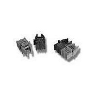
HFBR-2536 Avago Technologies US Inc., HFBR-2536 Datasheet - Page 9

HFBR-2536
Manufacturer Part Number
HFBR-2536
Description
RCVR OPT HI SPEED VERS LINK VERT
Manufacturer
Avago Technologies US Inc.
Datasheet
1.HFBR-2526Z.pdf
(12 pages)
Specifications of HFBR-2536
Data Rate
125MBd
Voltage - Supply
4.75 V ~ 5.25 V
Current - Supply
9mA
Applications
General Purpose
Function
The Receiverss convert a received optical signal to an analog output voltage.
Product
Receiver
Wavelength
650 nm
Maximum Rise Time
6.3 ns
Maximum Fall Time
6.3 ns
Maximum Output Current
25 mA
Operating Supply Voltage
- 0.5 V to + 6 V
Maximum Operating Temperature
+ 70 C
Minimum Operating Temperature
0 C
For Use With
Plastic Optical Fiber, Hard Clad Silica
Lead Free Status / RoHS Status
Contains lead / RoHS non-compliant
Power - Minimum Receivable
-
Lead Free Status / RoHS Status
Lead free / RoHS Compliant, Contains lead / RoHS non-compliant
9
125 Megabaud Versatile Link Receiver
HFBR-25X6Z Series
Description
The HFBR-25X6Z receivers contain a PIN photodiode
and transimpedance pre-amplifier circuit in a horizontal
(HFBR-2526Z) or vertical (HFBR-2536Z) blue housing, and
are designed to interface to 1mm diameter plastic opti-
cal fiber or 200 µm hard clad silica glass optical fiber. The
receivers convert a received optical signal to an analog
output voltage. Follow-on circuitry can optimize link per-
formance for a variety of distance and data rate require-
ments. Electrical bandwidth greater than 65 MHz allows
design of high speed data links with plastic or hard clad
silica optical fiber. Refer to Application Note 1066 for de-
tails for recommended interface circuits.
Absolute Maximum Ratings
Parameter
Storage Temperature
Operating Temperature
Lead Soldering Temperature
Cycle Time
Signal Pin Voltage
Supply Voltage
Output Current
CAUTION: The small junction sizes inherent to the design of this component increase the component’s susceptibility to damage from
electrostatic discharge (ESD). It is advised that normal static precautions be taken in handling and assembly of this component to
prevent damage and/or degradation which may be induced by ESD.
Symbol
V
T
V
T
I
CC
O
A
O
S
Min.
-0.5
-0.5
-40
0
Max.
+75
+70
260
6.0
V
10
25
CC
GROUND
GROUND
Unit
mA
°C
°C
°C
V
V
s
SEE NOTES 2, 4, 9
Reference
Note 1
4
3
2
1
V
GROUND
GROUND
SIGNAL
CC


