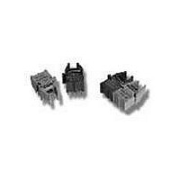
HFBR-2536 Avago Technologies US Inc., HFBR-2536 Datasheet - Page 3

HFBR-2536
Manufacturer Part Number
HFBR-2536
Description
RCVR OPT HI SPEED VERS LINK VERT
Manufacturer
Avago Technologies US Inc.
Datasheet
1.HFBR-2526Z.pdf
(12 pages)
Specifications of HFBR-2536
Data Rate
125MBd
Voltage - Supply
4.75 V ~ 5.25 V
Current - Supply
9mA
Applications
General Purpose
Function
The Receiverss convert a received optical signal to an analog output voltage.
Product
Receiver
Wavelength
650 nm
Maximum Rise Time
6.3 ns
Maximum Fall Time
6.3 ns
Maximum Output Current
25 mA
Operating Supply Voltage
- 0.5 V to + 6 V
Maximum Operating Temperature
+ 70 C
Minimum Operating Temperature
0 C
For Use With
Plastic Optical Fiber, Hard Clad Silica
Lead Free Status / RoHS Status
Contains lead / RoHS non-compliant
Power - Minimum Receivable
-
Lead Free Status / RoHS Status
Lead free / RoHS Compliant, Contains lead / RoHS non-compliant
3
Plastic Optical Fiber (1 mm POF) Transmitter Application Circuit: Performance of the HFBR-15X7Z transmitter in the recom-
mended application circuit (Figure 1) for POF; 1-125 MBd, 25°C.
Hard Clad Silica Fiber (200 µm HCS) Transmitter Application Circuit: Performance of the HFBR-15X7Z transmitter in the recom-
mended application circuit (Figure 1) for HCS; 1-125 MBd, 25°C.
Notes:
1. Average optical power is measured with an average power meter at 50% duty cycle, after 1 meter of fiber.
2. To allow the LED to switch at high speeds, the recommended drive circuit modulates LED light output between two non-zero power levels.
3. High and low level LED currents refer to the current through the HFBR-15X7Z LED. The low level LED “off” current, sometimes referred to as
Parameter
Average Optical Power 1 mm POF
Average Modulated Power 1 mm POF
Optical Rise Time (10% to 90%)
Optical Fall Time (90% to 10%)
High Level LED Current (On)
Low Level LED Current (Off )
Optical Overshoot - 1 mm POF
Transmitter Application Circuit
Current Consumption - 1 mm POF
Parameter
Average Optical Power 200 µm HCS
Average Modulated Power 200 µm HCS
Optical Rise Time (10% to 90%)
Optical Fall Time (90% to 10%)
High Level LED Current (On)
Low Level LED Current (Off)
Optical Overshoot - 200 µm HCS
Transmitter Application Circuit
Current Consumption - 200 µm HCS
The modulated (useful) power is the difference between the high and low level of light output power (transmitted) or input power (received),
which can be measured with an average power meter as a function of duty cycle (see Figure 3). Average Modulated Power is defined as one
half the slope of the average power versus duty cycle:
“hold-on” current, is prebias supplied to the LED during the off state to facilitate fast switching speeds.
Average Modulated Power =
Symbol
P
P
I
I
I
Symbol
mod
t
t
avg
F,H
F,L
CC
[P
r
f
P
P
I
I
I
avg
mod
t
F,H
t
F,L
CC
avg
r
f
@ 80% duty cycle - P
Typical
-11.3
-9.7
110
2.1
2.8
19
45
3
Typical
-14.6
-16.2
130
(2) [0.80 - 0.20]
3.1
3.4
60
30
6
avg
@ 20% duty cycle]
dBm
dBm
Unit
mA
mA
mA
ns
ns
%
dBm
dBm
Unit
mA
mA
mA
ns
ns
%
50% Duty
Condition
50% Duty
Condition
5 MHz
5 MHz
Cycle
5 MHz
5 MHz
Cycle
Note 1, Fig 3
Note 2, Fig 3
Note 1, Fig 3
Note 2, Fig 3
Figure 1
Figure 1
Note 3
Note 3
Note 3
Note 3
Note
Note


