4165100-XX Digital View Inc, 4165100-XX Datasheet - Page 6
4165100-XX
Manufacturer Part Number
4165100-XX
Description
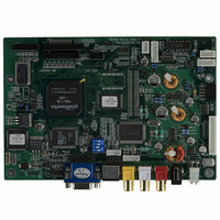
CTRLR SVP-1280 VGA-SXGA PNLS
Manufacturer
Digital View Inc
Datasheet
1.4165100-XX.pdf
(25 pages)
Specifications of 4165100-XX
Voltage - Input
12V
Voltage - Output
3.3V, 5V, 12V
Size / Dimension
7" L x 4.74" W (179mm x 120.4mm)
Power (watts)
10W
Operating Temperature
0°C ~ 60°C
Lead Free Status / RoHS Status
Contains lead / RoHS non-compliant
Other names
586-1004


CAUTION: Never connect or disconnect parts of the display system when the system is powered up as this may cause serious
damage.
CONNECTION
Connection and usage is quite straight forward (it is useful to have the relevant connection diagram available at this time):
1.
2.
3.
4.
5.
6.
7.
8.
9.
10. Power supply & Controller: Plug the DC 12V power in to the connector PP1.
11. Power on: Switch on the controller board and panel by using the OSD switch mount.
The red LED will light up when power on. The LED will change to green when VGA signal on.
General:
•
•
PC SETTINGS
The controller has been designed to take a very wide range of input signals however to optimize the PC’s graphics performance
we recommend choosing 60Hz vertical refresh rate – this will not cause screen flicker.
OPERATION
Once the system has been connected and switched on there are a number of functions available to adjust the display
image as summarized in the following sections. The settings chosen will be saved for each mode independently.
CONNECTION & OPERATION
LCD panel & Inverter: Connect the inverter (if it is not built-in the panel) to the CCFT lead connector of the LCD panel.
TTL type panels: Plug the signal cables direct to CN2, CN3 and CN4 (CN4 will not be used for 3x6-bit panel) on the
controller board. Plug the other end of cables to the LCD connector board (if connector board is required, otherwise the
signal can be direct plug to the LCD panel connector). Then plug the board connector to the LCD panel connector.
LVDS/PanelLink type panels: A LVDS/PanelLink transmitter board is required. Plug the transmitter board to CN2, CN3 &
CN4. Then insert the LCD signal cable with controller end to the connector on the transmitter board. Insert the panel end
of the cable the LCD panel connector.
Inverter & Controller: Plug the inverter cable to CNB1 and CNA1 (if necessary). Plug another end to the connector on
the inverter.
Function switch & Controller: Plug the OSD switch mount cable to CNC1 on the controller board and another to the
OSD switch mount.
LED & Controller: Plug in a 3-way with dual colour LED to connector LED1 on the controller board.
IR & Controller: Plug in a 3-way with IR sensor to connector IR1 on the controller board.
Jumpers & Switches: Check all jumpers and switches (SW1) are set correctly. Details referring the connection diagram
(a separate document) or the jumpers and switches setting table (in the following section).
Jumpers & Inverter & Panel voltage: Particularly pay attention to the settings of JA3, JA5, JB2 and JB3. JB2 & JB3 are
used for inverter control (read inverter specification and information on the jumper table to define the correct settings).
JA3 & JA5 are used for panel voltage input (read panel specification and information on the jumper table to define the
correct settings).
VGA cable & Controller: Plug the VGA cable to the connector P1 on the controller board.
If you are using supplied cables & accessories, ensure they are correct for the model of panel and controller.
If you are making your own cables & connectors refer carefully to both the panel & inverter specifications and the section
in this manual, “Connectors, Pinouts & Jumpers” to ensure the correct pin to pin wiring.
6
Related parts for 4165100-XX
Image
Part Number
Description
Manufacturer
Datasheet
Request
R

Part Number:
Description:
POST BIND STRIP 5 1/2"L F-GLASS
Manufacturer:
Keystone Electronics
Datasheet:

Part Number:
Description:
KIT OSD BRD W CBL DIGITAL POT
Manufacturer:
Digital View Inc
Datasheet:

Part Number:
Description:
Display Modules & Development Tools OSD DIGITAL I/F BRD 300MM CABLE
Manufacturer:
Digital View Inc
Datasheet:
Part Number:
Description:
Display Modules & Development Tools Digital OSD Kit
Manufacturer:
Digital View Inc
Datasheet:
Part Number:
Description:
Audio DSPs M3-310 Player w/LVDS & TTL Output
Manufacturer:
Digital View Inc


Part Number:
Description:
CABLE LVDS PANEL 460MM ROHS
Manufacturer:
Digital View Inc
Datasheet:
Part Number:
Description:
Audio DSPs M3-310 Player w/LVDS & TTL Output
Manufacturer:
Digital View Inc

Part Number:
Description:
BOARD PC/DVI INTERFACE ALR-1400
Manufacturer:
Digital View Inc

Part Number:
Description:
CTLR DVI-2560 DUAL LINK DVI 24V
Manufacturer:
Digital View Inc