4165100-XX Digital View Inc, 4165100-XX Datasheet - Page 4
4165100-XX
Manufacturer Part Number
4165100-XX
Description
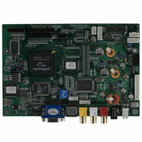
CTRLR SVP-1280 VGA-SXGA PNLS
Manufacturer
Digital View Inc
Datasheet
1.4165100-XX.pdf
(25 pages)
Specifications of 4165100-XX
Voltage - Input
12V
Voltage - Output
3.3V, 5V, 12V
Size / Dimension
7" L x 4.74" W (179mm x 120.4mm)
Power (watts)
10W
Operating Temperature
0°C ~ 60°C
Lead Free Status / RoHS Status
Contains lead / RoHS non-compliant
Other names
586-1004


This controller is designed for monitor and custom display projects using 1280 x 1024 or 1024 x 768 resolution TFT panels with
a VGA, SVGA, XGA or SXGA signal input. The following provides some guidelines for installation and preparation of a finished
display solution.
Preparation: Before proceeding it is important to familiarize yourself with the parts making up the system and the various
connectors, mounting holes and general layout of the controller. As much as possible connectors have been labeled. Guides
to connectors and mounting holes are shown in the following relevant sections.
1.
2.
3.
4.
5.
6.
7.
8.
9.
10. IR sensor: It is an optional part only, can be unconnected if not using IR remote control.
11. Audio add-on board: With the optional audio add-on board it is possible to control volume through the OSD menu. The
12. VGA Input Cable: As this may affect regulatory emission test results and the quality of the signal to the controller a
•
•
•
•
•
•
•
ASSEMBLY NOTES
LCD Panel: This controller is for TFT panels with 3.3V, 5V or 12V TTL or LVDS/TMDS interface. For LVDS/TMDS a
separate add-on board is required. Due to the variation between manufacturers panels signal timing and other panel
characteristics, factory setup and confirmation should be obtained before connecting to a panel. (NOTE: Check panel
power jumper settings before connection)
Controller: Handle the controller with care as static charge may damage electronic components. Make sure correct
jumper and dip switches settings to match the target LCD panel.
LCD connector board: Different makes and models of LCD panel require different panel signal connectors and different
pin assignments.
WIRING NOTE: If panels of less than 3 x 8 bit are used, eg 3 x 6 bit, then connection of panel signal high value should
correspond to the controllers highest bit. For example for a 6 bit panel R5 (Red data bit) on the panel should connect to
R7 on the controller, in this case R1 & R0 on the controller will not be connected. Same for Green & Blue.
LCD signal cables: In order to provide a clean signal it is recommended that LCD signal cables should not longer than
33cm (13 inches). If loose wire cabling is utilised these can be made into a harness with cable ties. Care should be taken
when placing the cables to avoid signal interference. Additionally it may be necessary in some systems to add ferrite
cores to the cables to minimise signal noise.
Inverter: This will be required for the backlight of an LCD, some LCD panels have an inverter built in. As LCD panels may
have 1 or more backlight tubes and the power requirements for different panel backlights may vary it is important to match
the inverter in order to obtain optimum performance. See Application notes for more information on connection.
Inverter Cables: Different inverter models require different cables and different pin assignment. Make sure correct cable
pin out to match inverter. Using wrong cable pin out may damage the inverter.
Function Controls: The following section discusses the controls required and the section on connectors provides the
detail. The controls are minimal: On/Off, Backlight Brightness (depends on inverter), OSD (5 momentary buttons) analog
VR type or (8 momentary buttons) digital type.
Function controls cable: The cables to the function switches should be of suitable quality and length so that impedance
does not affect performance. Generally lengths up to 1 meter (3 feet) should be acceptable.
Status LED: The pin direction of the LED should be corrected for right colour indication. Red colour stands for standby.
Green colours stands for signal on. The status LED is an optional part only, can be unconnected.
audio board fits on the right hand edge of the main controller.
suitably shielded cable should be utilized.
AV cables: Standard Composite or S-video cables can be used. Reasonable quality cable should be used to avoid image
quality degradation.
Power Input: 12V DC is required, this should be a regulated supply. The power rating is depending on the panel and
inverter used. Normally, power supply with 3.5Amp current output should enough for most of 4x CCFT panels. Although
the controller provides power regulation for the LCD power this does not relate to the power supplied to the backlight
inverter. If an unregulated power supply is provided to an inverter any fluctuations in power may affect operation,
performance and lifetime of the inverter and or backlight tubes.
Power output: Note the controller has an overall 3Amp current limit and the current available from the auxiliary power
output will be dependent on the power input and other system requirements.
Power Safety: Note that although only 12VDC is required as ‘power-in’ a backlight inverter for panel backlighting
produces significantly higher voltages (the inverter does not connect to the ground plane). We strongly advise appropriate
insulation for all circuitry.
EMI: Shielding will be required for passing certain regulatory emissions tests. Also the choice of external Controller to PC
signal cable can affect the result.
Ground: The various PCB mounting holes are connected to the ground plane.
Servicing: The board is not user serviceable or repairable. Warranty does not cover user error in connecting up to the
controller and is invalidated by unauthorized modification or repairs.
4
Related parts for 4165100-XX
Image
Part Number
Description
Manufacturer
Datasheet
Request
R

Part Number:
Description:
POST BIND STRIP 5 1/2"L F-GLASS
Manufacturer:
Keystone Electronics
Datasheet:

Part Number:
Description:
KIT OSD BRD W CBL DIGITAL POT
Manufacturer:
Digital View Inc
Datasheet:

Part Number:
Description:
Display Modules & Development Tools OSD DIGITAL I/F BRD 300MM CABLE
Manufacturer:
Digital View Inc
Datasheet:
Part Number:
Description:
Display Modules & Development Tools Digital OSD Kit
Manufacturer:
Digital View Inc
Datasheet:
Part Number:
Description:
Audio DSPs M3-310 Player w/LVDS & TTL Output
Manufacturer:
Digital View Inc


Part Number:
Description:
CABLE LVDS PANEL 460MM ROHS
Manufacturer:
Digital View Inc
Datasheet:
Part Number:
Description:
Audio DSPs M3-310 Player w/LVDS & TTL Output
Manufacturer:
Digital View Inc

Part Number:
Description:
BOARD PC/DVI INTERFACE ALR-1400
Manufacturer:
Digital View Inc

Part Number:
Description:
CTLR DVI-2560 DUAL LINK DVI 24V
Manufacturer:
Digital View Inc