4165100-XX Digital View Inc, 4165100-XX Datasheet
4165100-XX
Specifications of 4165100-XX


Related parts for 4165100-XX


4165100-XX Summary of contents
Page 1
... Connectors, pinouts & jumpers – Essential connection information 18. Controller dimensions 19. Application notes 20. Troubleshooting 21. Specifications 24. Warranty, Caution & Limitation of Liability, Trademarks 25. Contact details It is essential that these instructions are read and understood before connecting or powering up this controller. Model: SVP-1280 Part number : 4165100-XX INSTRUCTIONS 1 ...
Page 2
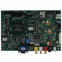
Introduction Designed for LCD monitor and other flat panel display applications the SVP-1280 controller provides an auto-input synchronization and easy to use interface controller for: TFT (active matrix) LCD panels of 1280x1024, 1024x768, 800x600 and 640x480 resolutions; Computer video signals ...
Page 3
SYSTEM DESIGN A typical LCD based display system utilising this controller is likely to comprise the following: Summary: 1. LCD panel 2. LCD controller card, SVP-1280 3. LCD panel connector board for LCD signal cable (if necessary) 4. LCD signal ...
Page 4
ASSEMBLY NOTES This controller is designed for monitor and custom display projects using 1280 x 1024 or 1024 x 768 resolution TFT panels with a VGA, SVGA, XGA or SXGA signal input. The following provides some guidelines for installation and ...
Page 5
Controller Mounting recommended that a clearance of at least 10mm is provided above and 5mm below the controller when mounted. Additionally consideration should be given to: • Electrical insulation. • Grounding. • EMI shielding. • Cable management. ...
Page 6
CONNECTION & OPERATION CAUTION: Never connect or disconnect parts of the display system when the system is powered up as this may cause serious damage. CONNECTION Connection and usage is quite straight forward (it is useful to have the relevant ...
Page 7
LCD DISPLAY SYSTEM SETTINGS NOTE: By way of explanation the following refers to a set of sample buttons that may be obtained as an option. In addition to power on/off and connection for backlight brightness the controller provides an On ...
Page 8
Frequency and Phase : Frequency Phase Picture Type : Motion / Still Video System : Select video system and input signals AUTO : automatic detection of NTSC and PAL system (not applicable in SECAM system) NTSC / NTSC 4.43 : ...
Page 9
Language : Select OSD menu language display 1. English 2. Danish 3. Chinese Video source : Select the input video signal Analog RGB / Component Video / Composite Video / S-Video Utilities : User Setting : User Timeout DPMS Display ...
Page 10
RS-232 serial control (Baud rate = 2400 bps) The OSD function can be controlled through send HEX code with the following button mapping table. MENU 0xf7 SEL_DN 0xfa SEL_UP 0xfb + 0xfc - 0xfd Volume 0x80 Brightness 0x81 Contrast 0x82 ...
Page 11
MANUAL & REMOTE CONTROL The following table shows the comparison of functions available from different controls: Operation One for All Menu Power - Mute Select + Ch+ Select - Ch- Setting + Vol+ Setting - Vol- Other multi-system IR transmitters ...
Page 12
CONNECTORS, PINOUTS & JUMPERS The various connectors are: Summary: Connectors Ref Purpose CN2 Panel signal CN3 Panel signal CN4 Panel signal CN7 Audio board connector CN8 RS-232 serial control CN10 Panel signal CNA1 Auxiliary power output CNB1 Backlight inverter CNC1 ...
Page 13
Summary: Jumpers setting Ref Purpose JA1 On board +5V logic power enable JA2 On board +3.3V logic power enable JA3 Panel power voltage select CAUTION: Incorrect setting can damage panel JA5 +12V panel power JA7 +12V power source on connector ...
Page 14
CN2 – Panel connector: HIROSE DF11-28DP-2DSA (Matching type : DF11-28DS-2C) PIN SYMBOL 1 GND 2 GND 3 ER2 4 OR2 5 ER3 6 OR3 7 ER4 8 OR4 9 ER5 10 OR5 11 EG2 12 OG2 13 EG3 14 OG3 ...
Page 15
CN4 – Panel connector: HIROSE DF11-20DF-2DSA (Matching type : DF11-20DS-2C) PIN SYMBOL 1 GND 2 GND ER0 6 OR0 7 ER1 8 OR1 9 EG0 10 OG0 11 EG1 12 OG1 13 EB0 14 OB0 15 EB1 ...
Page 16
CNB1 – Backlight inverter connector: JST B5B-XH-A (Matching type : XHP-5) PIN SYMBOL 1 GND 2 VBKL 3 BLCTRL 4 BVR_WIP 5 BVR_A CNC1 – Function controls connector: JST B12B-XH-A (Matching type : XHP-12) PIN SYMBOL 1 PSWIN 2 SW_ON ...
Page 17
IR1 – Infra-Red sensor connector: JST B3B-XH-A (Matching type : XHP-3) PIN SYMBOL 1 GND 2 STDBY_Vcc 3 IR Data LED1 – Status LED connector: 3-pin header PIN Analog VGA way connector ...
Page 18
CONTROLLER DIMENSIONS The maximum thickness of the controller is 20.6mm with or without video add-on board (measured from bottom of PCB to top of components, including any underside components & leads). We recommend clearances of: • 5mm from bottom of ...
Page 19
APPLICATION NOTES USING THE CONTROLLER WITHOUT BUTTONS ATTACHED This is very straightforward: • Firstly setup the controller/display system with the buttons. With controls attached and display system active make any settings for colour, tint and image position as required then ...
Page 20
TROUBLESHOOTING General A general guide to troubleshooting a flat panel display system it is worth considering the system as separate elements, such as: Controller (jumpers, PC settings) Panel (controller, cabling, connection, panel, PC settings) Backlight (inverter, cabling, backlight tubes) Cabling ...
Page 21
SPECIFICATIONS Panel compatibility No. of colours Signal Level Panel signal Vertical refresh rate Dot clock (pixel clock) maximum Graphics formats Graphics auto mode detect Standard input at source (analog RGB) Video formats Video inputs Functions display OSD menu functions OSD ...
Page 22
Graphic/Video Modes Supported Mode Resolution Clk [MHz] E1_70 640x350 25.175 E1_70 640x350 25.175 E1_70 640x350 25.175 E1_85 640x350 31.500 E1_85 640x350 31.500 E1_85 640x350 31.500 E2_70 640x400 25.175 E2_70 640x400 25.175 E2_70 640x400 25.175 E2_85 640x400 31.500 E2_85 640x400 31.500 ...
Page 23
X_70 1024x768 75.000 X_70 1024x768 75.000 X_70 1024x768 75.000 X_72 1024x768 75.000 X_72 1024x768 75.000 X_72 1024x768 75.000 X_75 1024x768 78.750 X_75 1024x768 78.750 X_75 1024x768 78.750 X_87I 1024x768 43Hz 44.900 Interaced X_87I 1024x768 43Hz 44.900 Interaced X_87I 1024x768 43Hz ...
Page 24
WARRANTY The products are warranted against defects in workmanship and material for a period of one (1) year from the date of purchase provided no modifications are made to it and it is operated under normal conditions and in compliance ...
Page 25
... Sales: hksales@digitalview.com EUROPE Digital View Ltd 36 Mortimer Street London W1W 7RG UK Tel: (44) (0) 20 7631 2150 Sales: uksales@digitalview.com USA Digital View Inc. 18440 Technology Drive Building 130 Morgan Hill, California, 95037 USA Tel: (1) 408-782 7773 Fax: (1) 408-782 7883 Sales: ussales@digitalview.com WEBSITE www.digitalview.com Specifications subject to change without notice Revised: July, 2005 (SVP-1280 ...