VK162-12 Matrix Orbital, VK162-12 Datasheet - Page 18
VK162-12
Manufacturer Part Number
VK162-12
Description
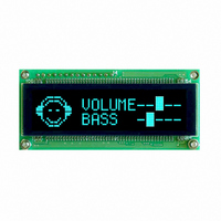
VFD DISPLAY 16X2 SER/I2C
Manufacturer
Matrix Orbital
Series
VK162-12r
Datasheet
1.VK162-12.pdf
(60 pages)
Specifications of VK162-12
Outline L X W X H
80.00mm x 36.00mm x 12.70mm
Viewing Area
51.40mm L x 11.40mm W
Display Format
16 x 2
Display Type
Character
Format
5 x 7 Dots
Character Size
4.76mm H x 2.46mm W
Interface
Serial
Operating Temperature
-20°C ~ 70°C
Product
Character Display Modules
Character Count X Line
16 x 2
Module Size (w X H X T)
80 mm x 36 mm x 12.7 mm
Operating Temperature Range
- 20 C to + 70 C
Dot Format
5 x 7
Viewing Area (w X H)
51.4 mm x 11.4 mm
Lead Free Status / RoHS Status
Lead free / RoHS Compliant
Voltage - Supply
-
Number Of Dots
-
Lead Free Status / Rohs Status
Details
Other names
635-1014


4 Communications
4.1 Introduction
4.1.1 I
single I
resistors, with a nominal value of 1K to 10K, are placed on the SCL and SDA communication lines coming
from pins two and three of the Data / Power Connector respectively. Data responses by the module are
automatically output via RS232, in case the host will be querying the module, it is necessary for the host to
inform the module that its responses are to be output via I
/160 / 0 to turn off auto transmission of data in RS232. This will keep the data in the buffer until the master
clocks a read of the slave. The I
8th or Least Significant Bit (LSB) bit designated as the read/write bit, a 0 designates a write address and a
1 designates a read address. The default read address of the display module will be 0x51, whereas the write
address is 0x50 by default. This address may be changed by using cmd 254 / 51 / <address>. The VK162-12
should only be sent addresses that are even (LSB is 0). When the I
the effective address is $50 (0101 0000) , since the LSB has to be 0 for an I
master wishes to read the VK162-12, the effective address is $51 (0101 0001), since the LSB has to be 1 for
an I
this Phillips I
When writing to the display module, the display will respond with a ACK when the write has successfully
been completed. However if the buffer has been filled, or the module is too busy processing data it will
respond with a NAK. When performing a multiple byte read within one I
the slave should be followed by an ACK to indicate that the master still needs data, and a NAK to indicate
that the transmission is over.
tions when writing I
sent (only needs to be sent once, so this can be done somewhere in init): 254 / 160 / 0 this command puts
the reply data in the I
output buffer, query commands that reply with more than 16 bytes cannot be read (eg cmd Get FileSystem
Directory)
Matrix Orbital
The commands listed in this chapter describe how to configure data flow on the VK162-12.
The VK162-12 is capable of communicating at 100 KHz in I
2
If we take a standard Phillips 7 bit address of $45 (100 0101), Matrix Orbital’s VK162-12 would describe
The unit does not respond to general call address ($00).
When communicating in I
The VK162-12 has some speed limitations, especially when run in I
* to be able to read the replies of query commands (eg. cmds 54, 55) the following command must be
* 3ms delay between the read commands
* 625us delay in between data bytes within a transaction is necessary
* 375us between transactions is necessary
C master read.
2
C communication line. However, in order to communicate via I
2
C Communication Summary
2
C address as $8A (1000 1010). The read address would be $8B (1000 1011).
2
C code:
2
C output buffer instead of the RS232 output buffer. Please note that due to a 16 byte
2
C the VK162-12 will send an ACK on the 9th clock cycle when addressed.
2
C data lines operate at 5V. The VK162-12 uses 8-bit addressing, with the
VK162-12
2
C. This can be done by sending command 254
2
C mode, with 127 units addressable on a
2
C master wishes to write to the display,
2
2
2
C you must first ensure that pull up
C mode. Here are some considera-
C transaction, each byte read from
2
C master write. When the I
2
14
C
Related parts for VK162-12
Image
Part Number
Description
Manufacturer
Datasheet
Request
R

Part Number:
Description:
VFD ALPHA/NUM DISPL 16X2 SER/I2C
Manufacturer:
Matrix Orbital
Datasheet:
Part Number:
Description:
VFD ALPHA/NUM DISPLAY 16X2
Manufacturer:
Matrix Orbital
Datasheet:
Part Number:
Description:
VFD ALPHA/NUM DISPLAY 16X2
Manufacturer:
Matrix Orbital
Datasheet:

Part Number:
Description:
DISPLAY
Manufacturer:
Matrix Orbital
Datasheet:
Part Number:
Description:
LCD ACCY VFD FILTER 20X2 BLUE
Manufacturer:
Matrix Orbital
Datasheet:
Part Number:
Description:
LCD ACCY VFD FILTER 20X2 RED
Manufacturer:
Matrix Orbital
Datasheet:
Part Number:
Description:
LCD ACCY VFD FILTER 20X2 GREEN
Manufacturer:
Matrix Orbital
Datasheet:
Part Number:
Description:
LCD ACCY VFD FILTER 20X4 BLUE
Manufacturer:
Matrix Orbital
Datasheet:
Part Number:
Description:
LCD ACCY VFD FILTER 20X4 RED
Manufacturer:
Matrix Orbital
Datasheet:
Part Number:
Description:
LCD ACCY VFD FILTER 20X4 GREEN
Manufacturer:
Matrix Orbital
Datasheet:

Part Number:
Description:
VFD ALPHA/NUM DISPL 20X2 SER/I2C
Manufacturer:
Matrix Orbital
Datasheet:

Part Number:
Description:
VFD ALPHA/NUM DISPL 16X2 SER/I2C
Manufacturer:
Matrix Orbital
Datasheet:
Part Number:
Description:
VFD ALPHA/NUM DISPL 20X2 SER/I2C
Manufacturer:
Matrix Orbital
Datasheet:
Part Number:
Description:
VFD ALPHA/NUM DISPLAY 16X2
Manufacturer:
Matrix Orbital
Datasheet: