MT9HTF6472AY-667D4 Micron Technology Inc, MT9HTF6472AY-667D4 Datasheet - Page 11
MT9HTF6472AY-667D4
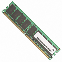
Manufacturer Part Number
MT9HTF6472AY-667D4
Description
MODULE DDR2 512MB 240-DIMM
Manufacturer
Micron Technology Inc
Datasheet
1.MT9HTF12872AY-40ED1.pdf
(44 pages)
Specifications of MT9HTF6472AY-667D4
Memory Type
DDR2 SDRAM
Memory Size
512MB
Package / Case
240-DIMM
Lead Free Status / RoHS Status
Lead free / RoHS Compliant
Speed
-
Other names
557-1303
MT9HTF6472AY-667D4
MT9HTF6472AY-667D4


Initialization
pdf: 09005aef80e6f860, source: 09005aef80e5b799
HTF9C32_64_128x72AG_2.fm - Rev. C 6/05 EN
10. Issue two or more REFRESH commands.
11. Issue a LOAD MODE command with LOW to A8 to initialize device operation (i.e., to
12. Issue a LOAD MODE command to the EMR to enable OCD default by setting Bits E7,
13. Issue a LOAD MODE command to the EMR to enable OCD exit by setting Bits E7, E8,
1. Apply power; if CKE is maintained below 20 percent of V
3. The voltage difference between any V
4. Wait a minimum of 400ns, then issue a PRECHARGE ALL command.
5. Issue a LOAD MODE command to the EMR(2) register. (To issue an EMR(2) com-
6. Issue a LOAD MODE command to the EMR(3) register. (To issue an EMR(3) com-
7. Issue a LOAD MODE command to the EMR register to enable DLL. To issue a DLL
8. Issue a LOAD MODE command for DLL Reset. 200 cycles of clock input is required to
9. Issue PRECHARGE ALL command.
The following sequence is required for power-up and initialization and is shown in
Figure 4, DDR2 Power-Up and Initialization, on page 12.
The DDR2 SDRAM device is now intialized and ready for normal operation 200 clocks
after DLL Reset in step 8.
abled. To guarantee R
must be applied to the ODT pin (all other inputs may be undefined). The time from
when V
than 20ms. At least one of the following two sets of conditions (A or B) must be met:
B. C
of 200µs after stable power and clock (CK, CK#), apply NOP or DESELECT commands
and take CKE HIGH
mand, provide LOW to BA0 and BA2, provide HIGH to BA1.)
mand, provide HIGH to BA0 and BA1, provide LOW to BA2.)
ENABLE command, provide LOW to BA1, BA2, and A0, provide HIGH to BA0. Bits E7,
E8, and E9 must all be set to 0.
lock the DLL. (To issue a DLL Reset, provide HIGH to A8 and provide LOW to BA2, BA1
and BA0.) CKE must be HIGH the entire time.
program operating parameters without resetting the DLL).
E8, and E9 to 1 and set all other desired parameters.
and E9 to 0 and set all other desired parameters.
A
256MB, 512MB, 1GB (x72, SR, ECC) 240-Pin DDR2 SDRAM UDIMM
. C
• V
• V
• V
• Apply V
• Apply V
• Apply V
ONDITION
ONDITION
DD
REF
DD
TT
first starts to power-up to the completion of V
, V
is limited to 0.95V MAX
tracks V
DD
DD
DD
DD
S
S
L and V
ET
ET
L before or at the same time as V
Q before or at the same time as V
before or at the same time as V
A
B
DD
TT
Q/2
DD
(ODT Resistance) is off, V
Q are driven from a single power converter output
11
Micron Technology, Inc., reserves the right to change products or specifications without notice.
DD
supply can not exceed 0.3V. For a minimum
DD
DD
TT
L.
REF
Q
and V
©2003, 2004, 2005 Micron Technology, Inc. All rights reserved.
must be valid and a low level
DD
REF
DD
Q must be equal to or less
Q, outputs remain dis-
Initialization
Related parts for MT9HTF6472AY-667D4
Image
Part Number
Description
Manufacturer
Datasheet
Request
R

Part Number:
Description:
IC SDRAM 64MBIT 133MHZ 54TSOP
Manufacturer:
Micron Technology Inc
Datasheet:

Part Number:
Description:
IC SDRAM 64MBIT 5.5NS 86TSOP
Manufacturer:
Micron Technology Inc
Datasheet:
Part Number:
Description:
IC SDRAM 64MBIT 200MHZ 86TSOP
Manufacturer:
Micron Technology Inc
Datasheet:
Part Number:
Description:
IC SDRAM 64MBIT 133MHZ 54TSOP
Manufacturer:
Micron Technology Inc
Datasheet:
Part Number:
Description:
IC SDRAM 128MBIT 133MHZ 54TSOP
Manufacturer:
Micron Technology Inc
Datasheet:

Part Number:
Description:
IC SDRAM 256MBIT 133MHZ 90VFBGA
Manufacturer:
Micron Technology Inc
Datasheet:
Part Number:
Description:
IC SDRAM 128MBIT 133MHZ 54TSOP
Manufacturer:
Micron Technology Inc
Datasheet:
Part Number:
Description:
IC SDRAM 256MBIT 133MHZ 54TSOP
Manufacturer:
Micron Technology Inc
Datasheet:

Part Number:
Description:
IC DDR SDRAM 512MBIT 6NS 66TSOP
Manufacturer:
Micron Technology Inc
Datasheet:
Part Number:
Description:
IC SDRAM 128MBIT 167MHZ 86TSOP
Manufacturer:
Micron Technology Inc
Datasheet:
Part Number:
Description:
IC SDRAM 128MBIT 143MHZ 86TSOP
Manufacturer:
Micron Technology Inc
Datasheet:

Part Number:
Description:
SDRAM 256M-BIT 1.8V 54-PIN VFBGA
Manufacturer:
Micron Technology Inc
Datasheet:
Part Number:
Description:
IC SDRAM 128MBIT 143MHZ 86TSOP
Manufacturer:
Micron Technology Inc
Datasheet:

Part Number:
Description:
IC SDRAM 128MBIT 125MHZ 54VFBGA
Manufacturer:
Micron Technology Inc
Datasheet:
Part Number:
Description:
IC SDRAM 128MBIT 125MHZ 54VFBGA
Manufacturer:
Micron Technology Inc
Datasheet: