W7CF128M1XA-H20PC-001.01 Wintec Industries, W7CF128M1XA-H20PC-001.01 Datasheet - Page 11
W7CF128M1XA-H20PC-001.01
Manufacturer Part Number
W7CF128M1XA-H20PC-001.01
Description
IC MEMORY
Manufacturer
Wintec Industries
Datasheet
1.W7CF128M1XA-H20PC-001.01.pdf
(50 pages)
Specifications of W7CF128M1XA-H20PC-001.01
Memory Size
128M bytes
Memory Type
CompactFLASH
Lead Free Status / RoHS Status
Lead free / RoHS Compliant
Other names
385-1037


WintecCF-W7CF-H_v2.2 ROHS
June 2006 Wintec Industries, Inc.
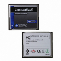
INDUSTRIAL GRADE CompactFlash
W7CFxxxA-H Series ROHS 6/6 Compliant
32MB – 8-GB
Table 7: Card Pin Explanation Cont.
-IOWR
(PC Card Memory Mode)
- IOWR
(PC Card I/O Mode)
- IOWR
(True IDE Mode)
-OE
(PC Card Memory Mode)
-OE
-ATA SEL
RDY/-BSY
(PC Card Memory Mode)
- IREQ
(PC Card I/O Mode)
-INTRQ
(True IDE Mode)
(PC Card I/O Mode)
(True IDE Mode)
Signal Name
Type
O
I
I
TM
Disk
Pin #
35
37
9
This signal is not used in this mode.
The I/O Write strobe pulse is used to clock I/O data on the
Card Data bus into the Compact Flash controller registers
when the card is configured to use the I/O interface.
The clocking will occur on the negative to positive edge of
the signal (trailing edge).
In True IDE Mode, this signal has the same function as in PC
Card I/O Mode.
This is an Output Enable strobe generated by the host
interface. It is used to read data from the Compact Flash Card
in Memory Mode and to read the CIS and configuration
registers.
In PC Card I/O Mode, this signal is used to read the CIS and
configuration registers.
To enable True IDE Mode this input should be grounded by
the host.
In Memory Mode this signal is set high when the Compact
Flash Card is ready to accept a new data transfer operation
and held low when the card is busy. The host memory card
socket must provide a pull-up resistor.
At power up and at Reset, the RDY/-BSY signal is held low
(busy) until the Compact Flash Card has completed its power
up or reset function. The RDY/-BSY signal is held high
(disabled from being busy) whenever the following condition
is true: The Compact Flash Card has been powered up with
+RESET continuously disconnected or asserted.
I/O Operation – After the Compact Flash Card has been
configured for I/O operation, this signal is used as – Interrupt
Request. This line is strobed low to generate a pulse mode
interrupt or held low for a level mode interrupt.
In True IDE Mode, this signal is the active high Interrupt
Request to the host.
Description
9
Related parts for W7CF128M1XA-H20PC-001.01
Image
Part Number
Description
Manufacturer
Datasheet
Request
R

Part Number:
Description:
MEMORY CARD COMPACTFLASH 128MB
Manufacturer:
Wintec Industries

Part Number:
Description:
HDD ENCLOSURE 3.5 USB 2.0 WHT
Manufacturer:
Wintec Industries
Datasheet:

Part Number:
Description:
HDD ENCLOSURE 2.5 USB 2.0 BK
Manufacturer:
Wintec Industries
Datasheet:

Part Number:
Description:
HDD ENCLOSURE 2.5 USB 2.0 WHT
Manufacturer:
Wintec Industries
Datasheet:

Part Number:
Description:
HDD ENCLOSURE 3.5 USB 2.0 BK
Manufacturer:
Wintec Industries
Datasheet:

Part Number:
Description:
EMBEDDED MODEM W/FUSE 33.6KBPS
Manufacturer:
Wintec Industries
Datasheet:

Part Number:
Description:
EMBEDDED MODEM W/FUSE 33.6KBPS
Manufacturer:
Wintec Industries
Datasheet:

Part Number:
Description:
EMBEDDED MODEM W/FUSE 56KBPS
Manufacturer:
Wintec Industries
Datasheet:

Part Number:
Description:
COMPACT FLASH INDUSTRIAL 1GB
Manufacturer:
Wintec Industries

Part Number:
Description:
COMPACT FLASH INDSTRL 512MB
Manufacturer:
Wintec Industries

Part Number:
Description:
COMPACT FLASH INDUSTRIAL 4GB
Manufacturer:
Wintec Industries

Part Number:
Description:
COMPACT FLASH INDUSTRIAL 1GB
Manufacturer:
Wintec Industries

Part Number:
Description:
COMPACT FLASH INDUSTRIAL 2GB
Manufacturer:
Wintec Industries

Part Number:
Description:
COMPACT FLASH INDUSTRIAL 2GB
Manufacturer:
Wintec Industries
Datasheet:

Part Number:
Description:
COMPACT FLASH INDUSTRIAL 4GB
Manufacturer:
Wintec Industries