W7CF128M1XA-H20PC-001.01 Wintec Industries, W7CF128M1XA-H20PC-001.01 Datasheet - Page 44
W7CF128M1XA-H20PC-001.01
Manufacturer Part Number
W7CF128M1XA-H20PC-001.01
Description
IC MEMORY
Manufacturer
Wintec Industries
Datasheet
1.W7CF128M1XA-H20PC-001.01.pdf
(50 pages)
Specifications of W7CF128M1XA-H20PC-001.01
Memory Size
128M bytes
Memory Type
CompactFLASH
Lead Free Status / RoHS Status
Lead free / RoHS Compliant
Other names
385-1037


WintecCF-W7CF-H_v2.2 ROHS
June 2006 Wintec Industries, Inc.
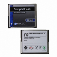
INDUSTRIAL GRADE CompactFlash
W7CFxxxA-H Series ROHS 6/6 Compliant
32MB – 8-GB
NEGATIVE TRUE SIGNALS APPEAR INVERTED ON THE BUS RELATIVE TO THE DIAGRAM.
ALL WAVEFORMS IN HIS DIAGRAM ARE SHOWN WITH THE ASSERTED STATE HIGH.
Notes:
(1) Device address consists of –CS0, -CS1, and A[02::00]
(2) Data consists of D[15::00] (16-bit) or D[07::00] (8-bit)
(3) –IOCS16 is shown for PIO modes 0, 1 and 2. For other modes, this signal is ignored.
(4) The negation of IORDY by the device is used to extend the PIO cycle. The determination of whether
(4-1) Device never negates IORDY: No wait is generated.
(4-2) Device starts to drive IORDY low before tA, but causes IORDY to be asserted before tA: No wait
(4-3) Device drives IORDY low before tA: wait generated. The cycle completes after IORDY is
the cycle is to be extended is made by the host after tA from the assertion of –IORD or –IOWR. The
assertion and negation of IORDY is described in the following three cases:
generated.
reasserted. For cycles where a wait is generated and –IORD is asserted, the device shall place read
data on D15-D00 for tRD before causing IORDY to be asserted.
Figure 20: True IDE Mode I/O Timing Diagram
TM
Disk
42
Related parts for W7CF128M1XA-H20PC-001.01
Image
Part Number
Description
Manufacturer
Datasheet
Request
R

Part Number:
Description:
MEMORY CARD COMPACTFLASH 128MB
Manufacturer:
Wintec Industries

Part Number:
Description:
HDD ENCLOSURE 3.5 USB 2.0 WHT
Manufacturer:
Wintec Industries
Datasheet:

Part Number:
Description:
HDD ENCLOSURE 2.5 USB 2.0 BK
Manufacturer:
Wintec Industries
Datasheet:

Part Number:
Description:
HDD ENCLOSURE 2.5 USB 2.0 WHT
Manufacturer:
Wintec Industries
Datasheet:

Part Number:
Description:
HDD ENCLOSURE 3.5 USB 2.0 BK
Manufacturer:
Wintec Industries
Datasheet:

Part Number:
Description:
EMBEDDED MODEM W/FUSE 33.6KBPS
Manufacturer:
Wintec Industries
Datasheet:

Part Number:
Description:
EMBEDDED MODEM W/FUSE 33.6KBPS
Manufacturer:
Wintec Industries
Datasheet:

Part Number:
Description:
EMBEDDED MODEM W/FUSE 56KBPS
Manufacturer:
Wintec Industries
Datasheet:

Part Number:
Description:
COMPACT FLASH INDUSTRIAL 1GB
Manufacturer:
Wintec Industries

Part Number:
Description:
COMPACT FLASH INDSTRL 512MB
Manufacturer:
Wintec Industries

Part Number:
Description:
COMPACT FLASH INDUSTRIAL 4GB
Manufacturer:
Wintec Industries

Part Number:
Description:
COMPACT FLASH INDUSTRIAL 1GB
Manufacturer:
Wintec Industries

Part Number:
Description:
COMPACT FLASH INDUSTRIAL 2GB
Manufacturer:
Wintec Industries

Part Number:
Description:
COMPACT FLASH INDUSTRIAL 2GB
Manufacturer:
Wintec Industries
Datasheet:

Part Number:
Description:
COMPACT FLASH INDUSTRIAL 4GB
Manufacturer:
Wintec Industries