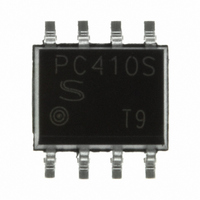
PC410S0NIP0F Sharp Microelectronics, PC410S0NIP0F Datasheet

PC410S0NIP0F
Specifications of PC410S0NIP0F
Related parts for PC410S0NIP0F
PC410S0NIP0F Summary of contents
Page 1
... PC410S0NIP0F Series ■ Description PC410S0NIP0F Series contains a LED optically cou- pled to an OPIC packaged pin mini-fl at. Input-output isolation voltage(rms) is 3.75 kV. High speed response (TYP. 10Mb/s) and CMR is MIN. 10kV/μs. ■ Features 1. 8 pin Mini-fl at package 2. Double transfer mold package (Ideal for Flow Soldering) 3 ...
Page 2
... Internal Connection Diagram ■ Truth table Input Enable Output ■ Outline Dimensions 1. Mini-fl at Package [ex. PC410S0NIP0F SHARP mark "S" Primary side mark ±0.05 ±0.076 1.27 0.406 Rank mark Date code ±0.127 5.080 MIN. 0.305 Product mass : approx. 0.15g ∗ N.C. ...
Page 3
... X 1998 K 2010 A 1999 L 2011 B 2000 M 2012 C 2001 repeats year cycle Country of origin Japan Rank mark With or without. 2nd digit Month of production Month Mark January 1 February 2 March 3 April 4 May 5 June 6 July 7 August 8 September 9 October O November N December D 3 PC410S0NIP0F Series Sheet No.: D2-A09001EN ...
Page 4
... 5mA 0.8V O(MAX) (pin ➇ ) and GND (pin ➄ ) near the device, when it measures the transfer characteristics and the output side CC 4 PC410S0NIP0F Series (Unless otherwise specifi =− 85˚ MIN. TYP. MAX. 1.3 1.8 − 1.4 1.5 1.75 10 − ...
Page 5
... Model Line-up Taping Package 1 500pcs/reel DIN EN60747-5-2 − Model No. PC410S0NIP0F PC410S0YIP0F Please contact a local SHARP sales representative to inquire about production status. Approved 5 PC410S0NIP0F Series Sheet No.: D2-A09001EN ...
Page 6
... L and wiring capacitance 350Ω = =5mA includes the probe and wiring capacitance PC410S0NIP0F Series t t PHL PLH 90 Timing diagram t t EHL ELH Timing diagram 1kV 0V 5V When the switch for LED sets O(MIN.) V When the switch for O(MAX ...
Page 7
... Ambient Temperature 85 75 100 125 (C) a Fig.7 High Level Output Current vs. Ambient Temperature 100 T =0˚ =−40˚C a 0.1 0.01 0.001 1.8 2 (V) F Fig.9 Input Threshold Current vs. Ambient Temperature I =6.4mA 100 ( PC410S0NIP0F Series 100 100 −40 −25 Ambient temperature T ( =5. =250μ = ...
Page 8
... R =1kΩ =4kΩ Fig.12-b Propagation Delay Time vs. 100 R =350Ω 100 (C) a Fig.13 Response Time vs. Ambient Temperature R =4kΩ PLH 60 80 100 ( PC410S0NIP0F Series V = =15pF L R =350Ω PLH t PHL Forward current I (mA) F Ambient Temperature R =1kΩ = =7.5mA =15pF ...
Page 9
... L −20 −60 −40 − Ambient temperature T Remarks : Please be aware that all data in the graph are just for reference and anot for guarantee. Fig.15 Erable Propagation Delay Time vs. Ambient Temperature 100 ( PC410S0NIP0F Series V = =3mA =350Ω ELH t EHL −60 −40 − ...
Page 10
... Please decide the input current which become 2 times of MAX. I Symbol MIN. TYP. MAX − − − − 4.5 − − − R 330 − − 40 − opr and GND near the device PC410S0NIP0F Series Unit 250 μ 0 − 4 000 Ω 85 ˚C . FHL Sheet No.: D2-A09001EN ...
Page 11
... Recommended foot print (reference) 7.49 1.9 (Unit : mm) 11 PC410S0NIP0F Series Sheet No.: D2-A09001EN ...
Page 12
... Please test the soldering method in actual condition and make sure the soldering works fi ne, since the im- pact on the junction between the device and PCB varies depending on the tooling and soldering conditions. Reflow 220˚C or more, 60s or less PC410S0NIP0F Series 4 (min) Sheet No.: D2-A09001EN ...
Page 13
... Specifi c brominated fl ame retardants such as the PBB and PBDE are not used in this product at all. This product shall not contain the following materials banned in the RoHS Directive (2002/95/EC). •Lead, Mercury, Cadmium, Hexavalent chromium, Polybrominated biphenyls (PBB), Polybrominated diphenyl ethers (PBDE). 13 PC410S0NIP0F Series Sheet No.: D2-A09001EN ...
Page 14
... Direction of product insertion ±0.05 ±0.10 ±0.1 ±0.05 1.75 8.0 2. ±0.05 ±0.1 ±0.1 3.7 6.3 Dimensions List φ21 Pull-out direction 14 PC410S0NIP0F Series J I (Unit : mm ±0.1 ±0.05 4.0 φ1.55 (Unit : mm 13.5 ±1.5 ±1 ±0.2 φ330 φ100 φ13 TYP. ±0.8 2.0 2.0 ±0.5 [Packing : 1 500pcs/reel] ...
Page 15
... SHARP. Express written permission is also required before any use of this publication may be made by a third party. · Contact and consult with a SHARP representative if there are any questions about the contents of this publi- cation. 15 PC410S0NIP0F Series Sheet No.: D2-A09001EN ...


