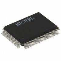
KS8993F Micrel Inc, KS8993F Datasheet - Page 72

KS8993F
Manufacturer Part Number
KS8993F
Description
IC CONV MED 10/100 3PORT 128PQFP
Manufacturer
Micrel Inc
Datasheet
1.KS8993F.pdf
(100 pages)
Specifications of KS8993F
Applications
*
Mounting Type
Surface Mount
Package / Case
128-MQFP, 128-PQFP
Number Of Primary Switch Ports
3
Internal Memory Buffer Size
32
Operating Supply Voltage (typ)
1.8/2.5/3.3V
Fiber Support
Yes
Integrated Led Drivers
Yes
Phy/transceiver Interface
MII/SNI
Power Supply Type
Analog/Digital
Package Type
PQFP
Data Rate (typ)
10/100Mbps
Vlan Support
Yes
Operating Temperature (max)
70C
Operating Temperature (min)
0C
Pin Count
128
Mounting
Surface Mount
Jtag Support
No
Operating Supply Voltage (max)
1.89/3.465V
Operating Temperature Classification
Commercial
Lead Free Status / RoHS Status
Lead free / RoHS Compliant
For Use With
KS8993F-EVAL - EVAL KIT EXPERIMENTAL KS8993F
Lead Free Status / RoHS Status
Not Compliant, Lead free / RoHS Compliant
Available stocks
Company
Part Number
Manufacturer
Quantity
Price
Part Number:
KS8993FA5
Manufacturer:
MICREL/麦瑞
Quantity:
20 000
Part Number:
KS8993FL
Manufacturer:
MICREL/麦瑞
Quantity:
20 000
Register 80 (0x50): My Status 1 (Terminal and Center side)
Register 81 (0x51): My Status 2
Micrel, Inc.
Bit
7
6
5
4
3
2
1
0
Bit
7-4
3
2
1
June 2009
Name
S7
S6
S5
S4
S3
S2
S1
S0
Name
S15 – S12
S11
S10
S9
R/W
RO
RO
RO
R/W
R/W
R/W
RO
RO
R/W
RO
R/W
R/W
RO
Description
1 = Terminal MC mode
0 = Center MC mode
Loop back mode indication
1 = In loop back state (CST1, CST2, UST1)
0 = Normal
Loss of optical signal notification
1 = use FEFI
0 = use maintenance frame
(Center side - CPU will update this bit
1 = Diagnostic Fail
0 = Normal operation
(Center side - CPU will update this bit.
UTP Link Down
1 = link down
0 = link up
(Center side - CPU will update this bit.
SD disable
1 = abnormal (no optical signal detected)
0 = normal (optical signal detected)
Power down
1 = power down
0 = normal operation
Description
Number of Physical interface making up the UTP link
0 = one
1 = greater than one
For Terminal MC mode, this bit indicates the auto negotiation
capability.
For Center MC mode, this bit must always be “0”.
1 = auto negotiation is supported
0 = auto negotiation is not supported
For Terminal MC mode, this bit indicates the UTP port’s DUPLEX
H-MC Link speed 1
H-MC Link Option
DIAG result
Reserved
Terminal side - Hardware will update this bit based on
Terminal side - This bit will be updated through DIAGF pin.)
Terminal side - This bit is read only and updated by hardware.)
external pin value)
72
hbwhelp@micrel.com
Default
0
1 (Terminal side)
0 (Center side)
0
0
DIAGF pin value
DIAGF (Ipd)
1
1
Inverse of PDD#
pin value
PDD# (Ipu)
Default
0
0
P2ANEN pin
value
(Terminal MC)
-----------------------
0
(Center MC)
0
or (408) 955-1690
M9999-062509
KS8993F/FL


