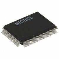
KS8993F Micrel Inc, KS8993F Datasheet - Page 66

KS8993F
Manufacturer Part Number
KS8993F
Description
IC CONV MED 10/100 3PORT 128PQFP
Manufacturer
Micrel Inc
Datasheet
1.KS8993F.pdf
(100 pages)
Specifications of KS8993F
Applications
*
Mounting Type
Surface Mount
Package / Case
128-MQFP, 128-PQFP
Number Of Primary Switch Ports
3
Internal Memory Buffer Size
32
Operating Supply Voltage (typ)
1.8/2.5/3.3V
Fiber Support
Yes
Integrated Led Drivers
Yes
Phy/transceiver Interface
MII/SNI
Power Supply Type
Analog/Digital
Package Type
PQFP
Data Rate (typ)
10/100Mbps
Vlan Support
Yes
Operating Temperature (max)
70C
Operating Temperature (min)
0C
Pin Count
128
Mounting
Surface Mount
Jtag Support
No
Operating Supply Voltage (max)
1.89/3.465V
Operating Temperature Classification
Commercial
Lead Free Status / RoHS Status
Lead free / RoHS Compliant
For Use With
KS8993F-EVAL - EVAL KIT EXPERIMENTAL KS8993F
Lead Free Status / RoHS Status
Not Compliant, Lead free / RoHS Compliant
Available stocks
Company
Part Number
Manufacturer
Quantity
Price
Part Number:
KS8993FA5
Manufacturer:
MICREL/麦瑞
Quantity:
20 000
Part Number:
KS8993FL
Manufacturer:
MICREL/麦瑞
Quantity:
20 000
Register 66 (0x42): Center Side Command
Register 67 (0x43): PHY-SW Initialize
Micrel, Inc.
Bit
7–5
4
3
2
1
0
Bit
7
6
5
June 2009
Name
P2 SPEED
P2 DUPLEX
P2 Auto
Negotiation
Name
Timer
Delay
Com4
Com3
Com2
Com1
Com0
R/W
R/W
R/W
R/W
R/W
R/W
R/W
R/W
R/W
R/W
R/W
Description
000 = Reserved (Do Not Use)
001 = 32us (default)
010 = 128us
011 = 256us
100 = 512us
101 = 1ms
110 = 2m
111 = 4ms
To send a maintenance frame, an external controller writes to these command
bits via the SMI, SPI, or I2C interface.
Other values : N/A
Note
0 0000 : No request
0 0001 : Send “Condition Inform Request” frame
0 0010 : Send “Loop Mode Start Request” frame
0 0100 : Send “Loop Mode Stop Request” frame
0 1000 : Send “Remote Command”. Here, the Maintenance frame will be made
1 0000 : Send “Indicate Center/Terminal MC Condition” frame. Usually,
Except for the “Indicate Center/Terminal MC Condition” frame, all
maintenance frames here are sent by the Center side MC only.
1 = Full duplex
1 = AN enable
Description
1 = 100Mbps
0 = 10Mbps
This bit share the same physical register as Reg. 2Ch bit 6.
0 = Half duplex
This bit share the same physical register as Reg. 2Ch bit 5.
0 = AN disable
This bit share the same physical register as Reg. 2Ch bit 7.
up of the “Condition Inform Request/Reply” frame, but the My Model
Info bits MM24-MM47 will be mapped to Registers 4Ah-4Ch, instead
of Registers 55h-57h.
“Indicate Center/Terminal MC Condition” frame will be sent
automatically. But this OAM frame can be sent manually using this
command.
66
hbwhelp@micrel.com
or (408) 955-1690
M9999-062509
Default
P2SPD pin
value during
reset
P2DPX pin
value during
reset
P2ANEN
pin value
during reset
KS8993F/FL
Default
001
0
0
0
0
0


