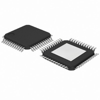
TZA1038HW,118 NXP Semiconductors, TZA1038HW,118 Datasheet - Page 15

TZA1038HW,118
Manufacturer Part Number
TZA1038HW,118
Description
IC DVD SIGNAL PROC 48-HTQFP
Manufacturer
NXP Semiconductors
Datasheet
1.TZA1038HW118.pdf
(45 pages)
Specifications of TZA1038HW,118
Applications
*
Mounting Type
Surface Mount
Package / Case
48-TQFP Exposed Pad, 48-eTQFP, 48-HTQFP, 48-VQFP
Lead Free Status / RoHS Status
Lead free / RoHS Compliant
Other names
935273843118
TZA1038HW-T
TZA1038HW-T
TZA1038HW-T
TZA1038HW-T
Available stocks
Company
Part Number
Manufacturer
Quantity
Price
Company:
Part Number:
TZA1038HW,118
Manufacturer:
NXP Semiconductors
Quantity:
10 000
Philips Semiconductors
7.2.8
Programming the registers of TZA1038HW is done via a
serial bus (see Fig.7). The circuitry is formed by a serial
input shift register and a number of registers that store the
data. The registers can always be programmed,
irrespective of STANDBY mode.
If required, the bus lines can be connected in parallel with
an I
line during SICL = HIGH. This means that other I
devices will not recognise any START or STOP
commands. Control words addressed to TZA1038HW
7.3
The TZA1038HW is controlled by serial registers. To keep programming fast and efficient, the control bits are sent in
16-bit words. Four bits of the word are used for the address and for each address there are 12 data bits.
Table 1 Overview of control parameters
2003 Sep 03
handbook, full pagewidth
Data path
G
G
G
GRFSUM
(A
BWRF
High speed advanced analog DVD signal
processor and laser supply
1
2
3
RFSUM
2
(A
(A
(A
SYMBOL
C-bus. The protocol needs no switching of the data
SICL
SIDA
SILD
1
2
3
Control registers
)
)
)
I
)
NTERFACE TO THE SYSTEM CONTROLLER
D0 D1 D2 D3 D4 D5
gain of first RF amplifier stage
(or linear amplification)
gain of second RF amplifier
stage (or linear amplification)
gain of third RF amplifier
stage (or linear amplification)
gain of RFSUM input stage (or
linear amplification)
bandwidth limitation in
RF path
PARAMETER
D6
D7 D8 D9 D10
Fig.7 Two word transmission.
2
C-bus
0, 6 and 12 dB (1
6, 12, 18 and 24 dB (2
0 to 13 dB in steps of 0.8 dB (1 to 4 )
(0.5 , 1 , 2 , 4 and 8 )
f
0(RF)
6, 0, 6, 12 and 18 dB
D11 A0 A1 A2
= 12 to 145 MHz
15
should go uniquely with the SILD signal. When
SILD = HIGH, the TZA1038HW will not respond to any
signal on SIDA or SICL.
During a transmission, the serial data is first stored in an
input shift register. At the rising edge of SILD, the content
of the input register is copied into the addressed register.
This is also the moment the programmed information
becomes effective.
The input pins have CMOS compatible threshold levels for
both 3.3 and 5 V supplies.
VALUES
A3
2 and 4 )
D0 D1 D2 D3
4
t load(H)
8 and 16 )
D4
REGISTER
A1
TZA1038HW
Product specification
14
A2
3
3
3
0
A3
MGW496
11 and 10
9 and 8
7 to 4
7 to 5
6 to 0
BITS


