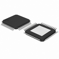
TZA1038HW,118 NXP Semiconductors, TZA1038HW,118 Datasheet - Page 13

TZA1038HW,118
Manufacturer Part Number
TZA1038HW,118
Description
IC DVD SIGNAL PROC 48-HTQFP
Manufacturer
NXP Semiconductors
Datasheet
1.TZA1038HW118.pdf
(45 pages)
Specifications of TZA1038HW,118
Applications
*
Mounting Type
Surface Mount
Package / Case
48-TQFP Exposed Pad, 48-eTQFP, 48-HTQFP, 48-VQFP
Lead Free Status / RoHS Status
Lead free / RoHS Compliant
Other names
935273843118
TZA1038HW-T
TZA1038HW-T
TZA1038HW-T
TZA1038HW-T
Available stocks
Company
Part Number
Manufacturer
Quantity
Price
Company:
Part Number:
TZA1038HW,118
Manufacturer:
NXP Semiconductors
Quantity:
10 000
Philips Semiconductors
7.2.4
The TZA1038HW provides differential phase detection to
support DVD in various ways:
Input signals for DPD are taken from input pins A to D after
the first gain stage G
by means of a programmable lead/lag filter. Additionally, a
programmable low-pass filter is available to improve the
signal quality under noisy signal conditions at lower
speeds. For further signal improvements the DPD pulse
stretcher can be programmed to higher values at lower
speeds.
The DPD signal is low-pass filtered by two internal
capacitors. The signal is then fed to pins S1 and S2, or
directed via the drop-out concealment circuit to the outputs
(see Section 7.5).
7.2.4.1
A special function is built in for compatibility with drop-out
detection strategies, based on level detection in the
S1 and S2 signals. When using DPD in a fundamental
way, there is no representation of mirror level information
from the light pen.
When the drop-out concealment function is enabled
(bit DOCEN = 1), a portion of the Central Aperture (CA)
signal is added to S1 and S2. Also, when the CA signal
drops below the DOC threshold, the DPD signal is
gradually attenuated.
The DPD detection cannot work properly when the input
signal becomes very small. The output of the DPD may
then show a significant offset. The DOC may not conceal
this offset completely because:
For details see Section 7.5.5.2
7.2.4.2
The TZA1038HW can also provide radial information by
means of push-pull signals (from the photodiode inputs) or
2003 Sep 03
DPD2 with four channels programmed to be active gives
DPD as required in the standard specification
Two of the four channels can be excluded from the DPD
for pick-ups with an alternative photodiode arrangement
An increase in performance, dedicated for DVD+RW,
can be obtained by using the DPD4 method. Then two
truly separated phase detectors are active. After the
phase detection of the two input pairs the result is
summed.
DOC is gradually controlled from the CA signal
The CA signal may not become 0 during disc-defect.
High speed advanced analog DVD signal
processor and laser supply
D
IFFERENTIAL PHASE DETECTION
Drop-out concealment
Push-pull and three-beam push-pull
1
(see Fig.3). Pre-emphasis is applied
13
in a three-spot optical system with Three-Beam Push-Pull
(TBPP). The built-in multiplexer gives a flexible method of
dealing with many detector arrangements. For push-pull,
the input signals are taken from channels A to D. There is
also a command that switches off channels B and C,
leaving channels A and D for push-pull
(bits RT_mode[2:0]).
For TBPP, the input signal is taken from channels E and F,
irrespective of bit RFSUM setting.
7.2.4.3
This option cancels offsets due to beam landing. A factor
can be programmed to re-balance the signal gain between
channels S1 and S2. In a simplified form this can be
described as:
Factor
with 1.0 as the balanced condition (bits [3:0]).
7.2.4.4
A provision is made to compensate electrical offset from a
light pen. The offset voltage from the light pen can be
positive or negative. In general, the offset between any two
channels is smaller than the absolute offsets. As negative
input signals cannot be handled by the TZA1038HW
internal servo channels, a two-step approach is adopted:
The range of both DACs can be increased by a factor of
three to compensate for higher offset values by means of
control parameter bit SERVOOS.
With a switched-off laser, the result of the offset
cancellation can be observed at each corresponding
output pin, OA to OD, S1 and S2, or via a built-in
multiplexer to pin OCENTRAL (central channels only).
See registers 11 to 13 for DAC and multiplexer control.
S1 = A
S2 = A
A coarse DAC, common to all the input channels, adds
an offset that shifts the input signals in positive direction
until all inputs are 0. The DAC used (LF
2-bit resolution (bits LF
A fine setting per channel is provided to cancel the
remainder of the offset between the channels. This is
achieved by DACs subtracting the DC component from
the signals and bringing the inputs to approximately zero
offset (within
have a 4-bit resolution.
LFR
LFR
can be programmed in a range from 0.6 to 1.35,
Enhanced push-pull (dynamic offset
compensation for beam landing)
Offset compensation
(2
1 mV). The DACs (registers 11 to 13)
input left
)
input right.
OFF
[1:0]).
TZA1038HW
Product specification
OFFS
) has a


