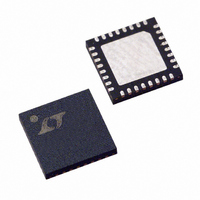
LTC3731CUH Linear Technology, LTC3731CUH Datasheet - Page 19

LTC3731CUH
Manufacturer Part Number
LTC3731CUH
Description
IC SW REG CTRLR SYNC BUCK 32QFN
Manufacturer
Linear Technology
Series
PolyPhase®r
Type
Step-Down (Buck)r
Datasheet
1.LTC3731CUHPBF.pdf
(32 pages)
Specifications of LTC3731CUH
Internal Switch(s)
No
Synchronous Rectifier
Yes
Number Of Outputs
1
Voltage - Output
0.6 ~ 6 V
Frequency - Switching
225kHz ~ 680kHz
Voltage - Input
4 ~ 36 V
Operating Temperature
0°C ~ 70°C
Mounting Type
Surface Mount
Package / Case
32-QFN
Lead Free Status / RoHS Status
Contains lead / RoHS non-compliant
Current - Output
-
Power - Output
-
Available stocks
Company
Part Number
Manufacturer
Quantity
Price
Company:
Part Number:
LTC3731CUH
Manufacturer:
Linear Technology
Quantity:
135
Company:
Part Number:
LTC3731CUH
Manufacturer:
LT
Quantity:
10 000
Part Number:
LTC3731CUH
Manufacturer:
LINEAR/凌特
Quantity:
20 000
Part Number:
LTC3731CUH#PBF
Manufacturer:
LINEAR/凌特
Quantity:
20 000
Part Number:
LTC3731CUH#TRPBF
Manufacturer:
LINEAR/凌特
Quantity:
20 000
APPLICATIO S I FOR ATIO
The value of the soft-start capacitor C
scaled with output current, output capacitance and load
current characteristics. The minimum soft-start capaci-
tance is given by:
The minimum recommended soft-start capacitor of
C
Current Foldback
In certain applications, it may be desirable to defeat the
internal current foldback function. A negative impedance
is experienced when powering a switching regulator.
That is, the input current is higher at a lower V
decreases as V
signed to accommodate a normal, resistive load having
increasing current draw with increasing voltage. The EAIN
pin should be artificially held 70% above its nominal
operating level of 0.6V, or 0.42V in order to prevent the IC
from “folding back” the peak current level. A suggested
circuit is shown in Figure 8.
The emitter of Q1 will hold up the EAIN pin to a voltage in
the absence of V
circuitry from reducing the peak output current. Remov-
ing the function in this manner eliminates the external
MOSFET’s protective feature under short-circuit condi-
tions. This technique will also prevent the short-circuit
latchoff function from turning off the part during a short-
circuit event and the peak output current will only be
limited to N • 75mV/R
SS
C
SS
= 0.1µF will be sufficient for most applications.
> (C
CALCULATE FOR
0.42V TO 0.55V
OUT
Figure 8. Foldback Current Elimination
)(V
IN
OUT
OUT
is increased. Current foldback is de-
U
that will prevent the internal sensing
) (10
SENSE
V
CC
U
–4
.
) (R
Q1
SENSE
V
EAIN
CC
W
LTC3731
SS
)
may need to be
3731 F08
U
IN
and
Undervoltage Reset
In the event that the input power source to the IC (V
drops below 4V, the RUN/SS capacitor will be discharged
to ground. When V
tor will be allowed to recharge and initiate another soft-
start turn-on attempt. This may be useful in applications
that switch between two supplies that are not diode
connected, but note that this cannot make up for the
resultant interruption of the regulated output.
Phase-Locked Loop and Frequency Synchronization
The IC has a phase-locked loop comprised of an internal
voltage controlled oscillator and phase detector. This
allows the top MOSFET of output stage 1’s turn-on to be
locked to the rising edge of an external source. The
frequency range of the voltage controlled oscillator is
±50% around the center frequency f
the PLLFLTR pin of 1.2V corresponds to a frequency of
approximately 400kHz. The nominal operating frequency
range of the IC is 225kHz to 680kHz.
The phase detector used is an edge sensitive digital type
that provides zero degrees phase shift between the
external and internal oscillators. This type of phase
detector will not lock the internal oscillator to harmonics
of the input frequency. The PLL hold-in range, ∆f
equal to the capture range, ∆f
The output of the phase detector is a complementary pair
of current sources charging or discharging the external
filter components on the PLLFLTR pin. A simplified block
diagram is shown in Figure 9.
If the external frequency (f
lator frequency, f
pulling up the PLLFLTR pin. When the external frequency
is less than f
down the PLLFLTR pin. If the external and internal fre-
quencies are the same, but exhibit a phase difference, the
current sources turn on for an amount of time correspond-
ing to the phase difference. Thus, the voltage on the
∆f
H
= ∆f
C
= ±0.5 f
OSC
, current is sunk continuously, pulling
OSC
CC
O
rises above 4V, the RUN/SS capaci-
, current is sourced continuously,
PLLIN
C
) is greater than the oscil-
:
O
. A voltage applied to
LTC3731
19
H
3731fb
, is
CC
)


