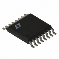
LT3825EFE#TRPBF Linear Technology, LT3825EFE#TRPBF Datasheet - Page 20

LT3825EFE#TRPBF
Manufacturer Part Number
LT3825EFE#TRPBF
Description
IC CNTRLR SYNC 16-TSSOP
Manufacturer
Linear Technology
Type
Flybackr
Datasheet
1.LT3825EFEPBF.pdf
(32 pages)
Specifications of LT3825EFE#TRPBF
Internal Switch(s)
No
Synchronous Rectifier
Yes
Number Of Outputs
1
Frequency - Switching
50kHz ~ 250kHz
Voltage - Input
12 ~ 18 V
Operating Temperature
-40°C ~ 125°C
Mounting Type
Surface Mount
Package / Case
16-TSSOP Exposed Pad, 16-eTSSOP, 16-HTSSOP
Power - Output
60W
Lead Free Status / RoHS Status
Lead free / RoHS Compliant
Current - Output
-
Voltage - Output
-
Available stocks
Company
Part Number
Manufacturer
Quantity
Price
APPLICATIONS INFORMATION
LT3825
Switching action commences and the converter begins to
deliver power to the output. Initially the output voltage is low
and the flyback voltage is also low, so C
of the LT3825 current (only a fraction comes from R
V
cally tens of milliseconds, the output voltage approaches
its desired value. The flyback winding then provides the
LT3825 supply current and the V
If C
old before stabilization and the LT3825 turns off. The V
node then begins to charge back up via R
on threshold, where the part again turns on. Depending
upon the circuit, this may result in either several on-off
cycles before proper operation is reached, or permanent
relaxation oscillation at the V
R
current greater than the maximum rated LT3825 start-up
current, and a worst-case maximum charging current less
than the minimum rated LT3825 supply current.
Make C
behavior described above. This is complicated to deter-
mine theoretically as it depends on the particulars of the
secondary circuit and load behavior. Empirical testing is
recommended. Note that the use of the optional soft-start
function lengthens the power-up timing and requires a
correspondingly larger value for C
If you have an available input voltage within the V
range, the internal wide hysteresis range UVLO function
becomes counterproductive. In such cases it is better to
operate the LT3825 directly from the available supply. In
20
and
CC
TR
R
R
TR
voltage continues to drop until after some time, typi-
is selected to yield a worst-case minimum charging
TR MAX
TR MIN
is undersized, V
(
(
TR
large enough to avoid the relaxation oscillatory
)
)
>
<
V
V
IN MAX
IN MIN
(
(
I
CC ST MAX
CC
)
)
I
CC MIN
(
–
–
reaches the V
(
V
V
CC ON MAX
_
CC ON MIN
CC
(
(
)
node.
)
CC
_
_
TR
voltage stabilizes.
.
)
CC
)
TR
turn-off thresh-
TR
supplies most
to the turn-
TR
CC
CC
.)
this case, use the LT3837 which is identical to the LT3825
except that it lacks the internal V
function. It is designed to operate directly from supplies
in the range of 4.5V to 19V. See the LT3837 data sheet for
further information.
The LT3825 has an internal clamp on V
19.5V. This provides some protection for the part in the
event that the switcher is off (UVLO low) and the V
is pulled high. If R
never attain this clamp voltage.
Control Loop Compensation
Loop frequency compensation is performed by connect-
ing a capacitor network from the output of the feedback
amplifier (V
cause of the sampling behavior of the feedback amplifier,
compensation is different from traditional current mode
switcher controllers. Normally only C
can be used to add a “zero” but the phase margin improve-
ment traditionally offered by this extra resistor is usually
already accomplished by the nonzero secondary circuit
impedance. C
frequency pole and is usually sized at 0.1 times C
In further contrast to traditional current mode switchers,
V
The dynamic nature of the clamped feedback amplifier
forms an effective track/hold type response, whereby the
V
“held” during the subsequent “switch-on” portion of the
C
C
voltage changes during the flyback pulse, but is then
pin ripple is generally not an issue with the LT3825.
C
Figure 5. V
VC2
pin) to ground as shown in Figure 5. Be-
can be used to add an additional high
TR
V
9
C
is sized correctly the part should
C
Compensation Network
3825 F05
C
VC2
CC
R
VC
C
VC
undervoltage lockout
CC
VC
of approximately
is required. R
CC
VC
node
.
3525fc
VC


