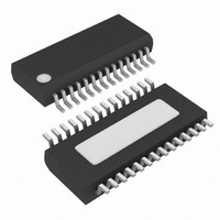
MAX1977EEI+ Maxim Integrated Products, MAX1977EEI+ Datasheet - Page 19

MAX1977EEI+
Manufacturer Part Number
MAX1977EEI+
Description
IC CNTRLR PS QUAD HI EFF 28QSOP
Manufacturer
Maxim Integrated Products
Datasheet
1.MAX1977EEIT.pdf
(32 pages)
Specifications of MAX1977EEI+
Applications
Controller, Notebook Computers
Voltage - Input
4.5 ~ 24 V
Number Of Outputs
4
Voltage - Output
3.3V, 5V, 2 ~ 5.5 V
Operating Temperature
0°C ~ 85°C
Mounting Type
Surface Mount
Package / Case
28-QSOP
Output Voltage
3.3 V, 2 V to 5.5 V
Input Voltage
6 V to 24 V
Mounting Style
SMD/SMT
Maximum Operating Temperature
+ 85 C
Minimum Operating Temperature
- 40 C
Case
SSOP
Dc
06+
Lead Free Status / RoHS Status
Lead free / RoHS Compliant
tinuous and discontinuous inductor-current operation
(also known as the critical conduction point):
where K is the on-time scale factor (see the On-Time
One-Shot (t
PFM/PWM crossover occurs, I
the peak-to-peak ripple current, which is a function of the
inductor value (Figure 5). For example, in the MAX1777
typical application circuit with V
L = 7.6µH, and K = 5µs, switchover to pulse-skipping
operation occurs at I
The crossover point occurs at an even lower value if a
swinging (soft-saturation) inductor is used.
The switching waveforms may appear noisy and asyn-
chronous when light loading causes pulse-skipping
operation, but this is a normal operating condition that
results in high light-load efficiency. Trade-offs in PFM
noise vs. light-load efficiency are made by varying the
inductor value. Generally, low inductor values produce
a broader efficiency vs. load curve, while higher values
result in higher full-load efficiency (assuming that the
coil resistance remains fixed) and less output voltage
ripple. Penalties for using higher inductor values
include larger physical size and degraded load-tran-
sient response (especially at low input voltage levels).
DC output accuracy specifications refer to the trip level of
the error comparator. When the inductor is in continuous
conduction, the output voltage has a DC regulation high-
er than the trip level by 50% of the ripple. In discontinu-
ous conduction (SKIP = GND, light load), the output
voltage has a DC regulation higher than the trip level by
approximately 1.5% due to slope compensation.
Figure 5. Pulse- Skipping/Discontinuous Crossover Point
I
LOAD SKIP
Supply Controllers for Notebook Computers
0
ON
∆i
∆t
ON-TIME
(
High-Efficiency, Quad Output, Main Power-
) section). The load-current level at which
=
V+ - V
)
______________________________________________________________________________________
=
OUT
L
LOAD
K V
×
2
×
OUT
= 0.96A or about 1/5 full load.
TIME
L
LOAD(SKIP)
_
⎛
⎜
⎝
OUT2
V
+ −
-I
PEAK
= 5V, V+ = 12V,
V
I
, is equal to 1/2
LOAD
V
+
OUT
= I
PEAK
_
/2
⎞
⎟
⎠
The low-noise, forced-PWM (SKIP = V
ables the zero-crossing comparator, which controls the
low-side switch on-time. Disabling the zero-crossing
detector causes the low-side, gate-drive waveform to
become the complement of the high-side, gate-drive
waveform. The inductor current reverses at light loads
as the PWM loop strives to maintain a duty ratio of
V
the switching frequency fairly constant, but it comes at
a cost: the no-load battery current can be 10mA to
50mA, depending on switching frequency and the
external MOSFETs.
Forced-PWM mode is most useful for reducing audio-
frequency noise, improving load-transient response,
providing sink-current capability for dynamic output
voltage adjustment, and improving the cross-regulation
of multiple-output applications that use a flyback trans-
former or coupled inductor.
Leaving SKIP unconnected or connecting SKIP to REF
activates a pulse-skipping mode with a minimum
switching frequency of 25kHz. This ultrasonic pulse-
skipping mode reduces audio-frequency modulation of
the power supply that may occur in Idle Mode at very
light loads. The transition to fixed-frequency PWM oper-
ation is automatic and occurs at the same point as in
Idle Mode. Ultrasonic pulse skipping occurs if no
switching has taken place within the last 28µs. DL_
turns on to induce a regulated negative current in the
inductor. DH_ turns on when the inductor current
reaches the regulated negative current limit. Starting
with a DL_ pulse greatly reduces the ripple current
when compared to starting with a DH_ pulse (Idle
Mode). The output voltage level determines the nega-
tive current limit.
Calculate the negative ultrasonic current-limit threshold
with the following equation:
where V
synchronous rectifier (MAX1999) or the current-sense
resistor value (MAX1777/MAX1977).
V
OUT
NEG
/V+. The benefit of forced-PWM mode is to keep
U
S
Minimum 25kHz Pulse-Skipping Mode
FB
=
I
> V
LX
×
REF
R
ON
, and R
=
(
V
ON
REF
V
ILIM
is the on-resistance of the
−
Forced-PWM Mode
V
_
(Ultrasonic Mode)
FB
)
×
CC
0 467
.
) mode dis-
V
19


