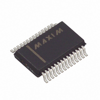
MAX1902EAI+ Maxim Integrated Products, MAX1902EAI+ Datasheet - Page 27

MAX1902EAI+
Manufacturer Part Number
MAX1902EAI+
Description
IC CNTRLR PWR SPLY LN 28-SSOP
Manufacturer
Maxim Integrated Products
Datasheet
1.MAX1904ETJ.pdf
(33 pages)
Specifications of MAX1902EAI+
Applications
Controller, Notebook Computers
Voltage - Input
4.2 ~ 30 V
Number Of Outputs
4
Voltage - Output
2.5 ~ 5 V
Operating Temperature
0°C ~ 85°C
Mounting Type
Surface Mount
Package / Case
28-SSOP
Output Voltage
3.3 V or 5 V or 2.5 V to 5.5 V
Output Current
5 A
Input Voltage
4.2 V to 30 V
Supply Current
5 uA
Switching Frequency
500 KHz
Mounting Style
SMD/SMT
Maximum Operating Temperature
+ 85 C
Minimum Operating Temperature
- 40 C
Lead Free Status / RoHS Status
Lead free / RoHS Compliant
performance. In most applications, the circuit will be
located on a multilayer board, and full use of the four or
more copper layers is recommended. Use the top layer
for high-current connections, the bottom layer for quiet
connections (REF, SS, GND), and the inner layers for
an uninterrupted ground plane. Use the following step-
by-step guide:
1) Place the high-power components (Figure 1, C1, C3,
Ideally, surface-mount power components are butted up
to one another with their ground terminals almost touch-
ing. These high-current grounds are then connected to
each other with a wide filled zone of top-layer copper so
they don’t go through vias. The resulting top layer “sub-
ground-plane” is connected to the normal inner-layer
ground plane at the output ground terminals, which
ensures that the IC’s analog ground is sensing at the sup-
ply’s output terminals without interference from IR drops
C4, Q1, Q2, L1, and R1) first, with their grounds
adjacent.
• Priority 1: Minimize current-sense resistor trace
• Priority 2: Minimize ground trace lengths in the
• Priority 3: Minimize other trace lengths in the high
500kHz Multi-Output, Low-Noise Power-Supply
Use >5mm-wide traces
CIN to high-side MOSFET drain: 10mm max
length
Rectifier diode cathode to low-side MOSFET:
5mm max length
LX node (MOSFETs, rectifier cathode, inductor):
15mm max length
lengths and ensure accurate current sensing with
Kelvin connections (Figure 9).
high-current paths (discussed below).
current paths.
______________________________________________________________________________________
Controllers for Notebook Computers
and ground noise. Other high-current paths should also
be minimized, but focusing primarily on short ground and
current-sense connections eliminates about 90% of all PC
board layout problems.
2) Place the IC and signal components. Keep the main
3) Use a single-point star ground where the input
Figure 9. Kelvin Connections for the Current-Sense Resistors
switching nodes (LX nodes) away from sensitive
analog components (current-sense traces and REF
capacitor). Place the IC and analog components on
the opposite side of the board from the power-
switching node. Important: the IC must be no more
than 10mm from the current-sense resistors. Keep
the gate-drive traces (DH_, DL_, and BST_) shorter
than 20mm and route them away from CSH_, CSL_,
and REF.
ground trace, power ground (sub-ground-plane), and
normal ground plane meet at the supply’s output
ground terminal. Connect both IC ground pins and all
IC bypass capacitors to the normal ground plane.
MAX1901/MAX1902/MAX1904
HIGH-CURRENT PATH
SENSE RESISTOR
27


