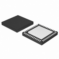
NCP4208MNR2G ON Semiconductor, NCP4208MNR2G Datasheet - Page 8

NCP4208MNR2G
Manufacturer Part Number
NCP4208MNR2G
Description
IC CTLR 8PH VR11.1 PMBUS 48-QFN
Manufacturer
ON Semiconductor
Datasheet
1.NCP4208MNR2G.pdf
(30 pages)
Specifications of NCP4208MNR2G
Applications
Controller, Intel VR11.1
Voltage - Input
4.7 ~ 5.75 V
Number Of Outputs
8
Voltage - Output
0.16 ~ 5 V
Operating Temperature
0°C ~ 85°C
Mounting Type
Surface Mount
Package / Case
48-TQFN Exposed Pad
Output Voltage
0.375 V to 1.6 V
Input Voltage
0.3 V to 6 V
Switching Frequency
1.5 MHz
Operating Temperature Range
0 C to + 85 C
Mounting Style
SMD/SMT
Duty Cycle (max)
100 %
Lead Free Status / RoHS Status
Lead free / RoHS Compliant
Available stocks
Company
Part Number
Manufacturer
Quantity
Price
Company:
Part Number:
NCP4208MNR2G
Manufacturer:
ON Semiconductor
Quantity:
1 200
Part Number:
NCP4208MNR2G
Manufacturer:
ON/安森美
Quantity:
20 000
ELECTRICAL CHARACTERISTICS
V
Power−Good Comparator
PWM Outputs
I
ALERT, FAULT Outputs
Analog / Digital Converter
Supply
1. Performance guaranteed over the indicated operating temperature range by design and/or characterization tested at T
2. Refer to Application Information section.
3. Values based on design and/or characterization.
Overvoltage Adjustment Range Low
Overvoltage Adjustment Range High
Output Low Voltage
Power−Good Delay Time
Crowbar Trip Point
Crowbar Delay Time
Output Low Voltage
Output High Voltage
Logic High Input Voltage
Logic Low Input Voltage
Hysteresis
SDA Output Low Voltage
Input Current
Input Capacitance
Clock Frequency
SCL Falling Edge to SDA Valid Time
Output Low Voltage
Output High Leakage Current
Total Unadjusted Error (TUE)
Differential Non−linearity (DNL)
Conversion Time
V
DC Supply Current
UVLO Turn−On Current
UVLO Threshold Voltage
UVLO Turn−Off Voltage
VCC3 Output Voltage
2
IN
C Interface
CC
During Soft−Start
VID Code Changing
VID Code Static
Crowbar Adjustment Range
Crowbar Reset Point
VID Code Changing
VID Code Static
duty cycle pulse techniques are used during testing to maintain the junction temperature as close to ambient as possible.
= (5.0 V) FBRTN − GND, for typical values T
Parameter
PWRGD_Hi Register = 11
PWRGD_Hi Register = 00
I
Internal Timer
Relative to DAC Output, PWRGD_Hi = 00
PWRGD_Hi Limit
Relative to FBRTN
Overvoltage to PWM going low
I
I
I
I
V
8 Bits
Averaging Enabled (32 averages)
V
V
V
V
I
PWRGD(SINK)
PWM(SINK)
PWM(SOURCE)
SDA
OUT
VCC3
OH
CC
SYSTEM
CC
CC
Rising
Falling
= 5.0 V
= −6 mA
= −6 mA
= 1 mA
A
= 13.2 V, R
= 25°C, for min/max values T
= −400 mA
= −4 mA
Test Conditions
= 400 mA
http://onsemi.com
SHUNT
= 340 W
8
A
= 0°C to 85°C; unless otherwise noted. (Notes 1 and 2)
V
V
V
V
t
C
V
V
IH(SDA,SCL)
IH(SDA,SCL)
OL(PWRGD)
CROWBAR
Symbol
CROWBAR
OL(PWM)
OH(PWM)
V
SCL, SDA
V
V
I
V
f
V
V
IH
UVLO
SCL
VCC
CC3
OL
OL
OH
; I
IL
−1.0
4.70
Min
100
200
150
250
100
4.0
2.1
9.0
3.0
±1.0
5.25
Typ
150
300
150
250
200
300
300
250
400
160
500
2.0
5.0
5.0
1.0
6.5
4.1
3.3
80
21
J
= T
Max
5.75
A
300
400
300
350
500
400
0.8
0.4
1.0
1.0
0.4
1.0
3.6
26
11
= 25_C. Low
Unit
LSB
kHz
mV
mV
mV
mV
mV
mV
mA
mA
ms
ms
mA
pF
mA
ms
ns
ms
ns
ms
%
V
V
V
V
V
V
V
V
V


