GNM314R72A102KD01D Murata Electronics North America, GNM314R72A102KD01D Datasheet - Page 50
GNM314R72A102KD01D
Manufacturer Part Number
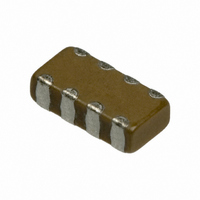
GNM314R72A102KD01D
Description
CAP 4-ARRAY 1000PF 100V X7R 1206
Manufacturer
Murata Electronics North America
Series
GNMr
Datasheet
1.GNM212R61A225MA01D.pdf
(151 pages)
Specifications of GNM314R72A102KD01D
Capacitance
1000pF
Voltage - Rated
100V
Dielectric Material
Ceramic
Number Of Capacitors
4
Circuit Type
Isolated
Temperature Coefficient
X7R
Tolerance
±10%
Mounting Type
Surface Mount
Package / Case
1206 (3216 Metric)
Height
0.031" (0.80mm)
Size / Dimension
0.126" L x 0.063" W (3.20mm x 1.60mm)
Lead Free Status / RoHS Status
Lead free / RoHS Compliant
Other names
490-3421-2


8
!Note
• This PDF catalog is downloaded from the website of Murata Manufacturing co., ltd. Therefore, it’s specifications are subject to change or our products in it may be discontinued without advance notice. Please check with our
• This PDF catalog has only typical specifications because there is no space for detailed specifications. Therefore, please approve our product specifications or transact the approval sheet for product specifications before ordering.
sales representatives or product engineers before ordering.
!Note
48
No.
10
11
Specifications and Test Methods
1
2
3
4
5
6
7
8
9
Capacitance
Temperature
Characteristics
Vibration
Resistance
Operating
Temperature
Rated Voltage
Appearance
Dimensions
Dielectric Strength
Insulation Resistance
(I.R.)
Capacitance
Dissipation Factor
(D.F.)
Adhesive Strength
of Termination
• Please read rating and !CAUTION (for storage, operating, rating, soldering, mounting and handling) in this catalog to prevent smoking and/or burning, etc.
• This catalog has only typical specifications because there is no space for detailed specifications. Therefore, please approve our product specifications or transact the approval sheet for product specifications before ordering.
Item
Appearance
Capacitance
D.F.
Y25 to W85D
See the previous pages.
No defects or abnormalities
Within the specified dimensions
No defects or abnormalities
More than 10,000MΩ
Within the specified tolerance
0.01 max.
Within Y 4,700
Within Y 4,700
No removal of the terminations or other defect should occur.
No defects or abnormalities
Within the specified tolerance
0.01 max.
W1,000
Y2,500
W500
Y1,000
ppm/ D (at Y 25 to W 20 D )
ppm/ D (at W 20 to W 85 D )
Specifications
Reference Temperature: 20°C
The rated voltage is defined as the maximum voltage which
may be applied continuously to the capacitor.
When AC voltage is superimposed on DC voltage, V
whichever is larger, should be maintained within the rated volt-
age range.
Visual inspection
Using calipers
No failure should be observed when 300% of the rated voltage
is applied between the terminations for 1 to 5 seconds, provid-
ed the charge/discharge current is less than 50mA.
The insulation resistance should be measured with a DC volt-
age not exceeding the rated voltage at 20D and 75%RH max.
and within 2 minutes of charging.
The capacitance/D.F. should be measured at 20D with
1T0.1kHz in frequency and 1T0.2Vrms in voltage.
The temperature coefficient is determined using the
capacitance measured in step 1 as a reference.
When cycling the temperature sequentially from step 1 through
5, the capacitance should be within the specified tolerance for
the temperature coefficient.
The capacitance change should be measured after 5 min. at
each specified temperature stage.
Solder the capacitor to the test jig (glass epoxy board) shown in
Fig.1 using a eutectic solder. Then apply 10N force in the
direction of the arrow.
The soldering should be done either with an iron or using the
reflow method and should be conducted with care so that the
soldering is uniform and free of defects such as heat shock.
Solder the capacitor to the test jig (glass epoxy board) in the
same manner and under the same conditions as (10).
The capacitor should be subjected to a simple harmonic motion
having a total amplitude of 1.5mm, the frequency being varied
uniformly between the approximate limits of 10 and 55Hz. The
frequency range, from 10 to 55Hz and return to 10Hz, should
be traversed in approximately 1 minute. This motion should be
applied for a period of 2 hours in each of 3 mutually perpendic-
ular directions (total of 6 hours).
GRM21
Type
Step
1
2
3
4
5
1.2
Test Method
a
Fig. 1
Continued on the following page.
Temperature (D)
Y25T3
c
20T2
20T2
85T3
20T2
4.0
b
Baked electrode or
copper foil
Solder resist
1.65
P-P
c
(in mm)
or V
O-P
,
C02E.pdf
07.2.6
Related parts for GNM314R72A102KD01D
Image
Part Number
Description
Manufacturer
Datasheet
Request
R

Part Number:
Description:
BUZZER PIEZO 25VP-P SMD
Manufacturer:
Murata Electronics North America

Part Number:
Description:
CAP 4-ARRAY 680PF 100V X7R 1206
Manufacturer:
Murata Electronics North America
Datasheet:
Part Number:
Description:
CAP 4-ARRAY 1800PF 100V X7R 1206
Manufacturer:
Murata Electronics North America
Datasheet:
Part Number:
Description:
CAP 4-ARRAY 68000PF 16V X7R 1206
Manufacturer:
Murata Electronics North America
Datasheet:

Part Number:
Description:
CAP CER 1000PF 50V 10% X7R 0402
Manufacturer:
Murata Electronics North America
Datasheet:
Part Number:
Description:
CAP CER 10000PF 16V 10% X7R 0402
Manufacturer:
Murata Electronics North America
Datasheet:

Part Number:
Description:
CAP 5.5-25PF 2.5X3.2MM SMD
Manufacturer:
Murata Electronics North America
Datasheet:

Part Number:
Description:
CAP 4.5-20PF 2.5X3.2MM SMD
Manufacturer:
Murata Electronics North America
Datasheet:

Part Number:
Description:
CAP 5.0-20PF 3.2X4.5MM SMD RED
Manufacturer:
Murata Electronics North America
Datasheet:

Part Number:
Description:
CAP 2.0-6.0PF 3.2X4.5MM SMD BLU
Manufacturer:
Murata Electronics North America
Datasheet:

Part Number:
Description:
CAP 1.4-3.0PF 3.2X4.5MM SMD BRN
Manufacturer:
Murata Electronics North America
Datasheet:

Part Number:
Description:
CAP 3.0-10PF 3.2X4.5MM SMD WHT
Manufacturer:
Murata Electronics North America
Datasheet:

Part Number:
Description:
CAP 2.0-6.0PF 4X4.5MM TOPADJ BLU
Manufacturer:
Murata Electronics North America
Datasheet:

Part Number:
Description:
CAP 8.5-40PF 4X4.5MM TOPADJ YEL
Manufacturer:
Murata Electronics North America
Datasheet:

Part Number:
Description:
CAP 8.0-45PF 2.5X3.2MM SMD
Manufacturer:
Murata Electronics North America
Datasheet: