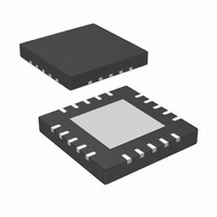
IR3082AMTRPBF International Rectifier, IR3082AMTRPBF Datasheet - Page 27

IR3082AMTRPBF
Manufacturer Part Number
IR3082AMTRPBF
Description
IC XPHASE CONTROL 9.6V 20-MLPQ
Manufacturer
International Rectifier
Series
XPhase™r
Datasheet
1.IR3082AMTRPBF.pdf
(33 pages)
Specifications of IR3082AMTRPBF
Applications
Processor
Current - Supply
12mA
Voltage - Supply
8.05 V ~ 16 V
Operating Temperature
0°C ~ 100°C
Mounting Type
Surface Mount
Package / Case
20-MLPQ
Ic Function
Control IC
Supply Voltage Range
8.05V To 16V
Operating Temperature Range
0°C To +100°C
Digital Ic Case Style
MLPQ
No. Of Pins
20
Filter Terminals
SMD
Supply Voltage Min
9.6V
Rohs Compliant
Yes
Controller Type
PWM
Frequency
1MHz
Package
20-Lead MLPQ
Circuit
X-Phase Control IC
Switch Freq (khz)
150kHz to 1.0MHz
Pbf
PbF Option Available
Lead Free Status / RoHS Status
Lead free / RoHS Compliant
Other names
IR3082AMTRPBFTR
IR3086A EXTERNAL COMPONENTS
PWM Ramp Resistor R
Set PWM ramp magnitude V
resistor R
Inductor Current Sensing Capacitor C
Choose C
Choose
R
Over Temperature Setting Resistors R
Use central over temperature setting and set the temperature threshold at 115 ºC, which corresponds the IC die
temperature of 116 ºC. Calculate the HOTSET threshold voltage corresponding to the temperature thresholds.
Phase Delay Timing Resistors R
The phase delay resistor ratios for phases 1 to 5 at 600kHz of switching frequencies are RAPHASE1=0.646,
RAPHASE2=0.400, RAPHASE3=0.158, RAPHASE4=0.291 and RAPHASE5=0.561starting from down-slope. Pre-
select RPHASE11=RPHASE21=RPHASE31=RPHASE41=RPHASE51= RPHASE61=20k
R
Bootstrap Capacitor C
Choose C
Decoupling Capacitors for Phase IC and Power Stage
Choose C
V
R
R
R
R
R
CS
CS-
HOTSET
PHASE22
PWMRMP
HOTSET
CS
PHASE
12
˜
,
600
12
2
L
C
. 0
0
Page 27 of 33
R
CS
25
4 .
˜
R
CS
. 4
PWMRMP
10
=13.3
CS+
1
BST
VCC
V
R
L
73
V
IN
˜
RA
HOTSET
3
R
BIAS
RA
˜
˜
=47nF and calculate R
˜
=0.1uF
=0.1uF, C
100
CS
10
11
220
PHASE
f
SW
PHASE
5 .
1
3
˜
V
˜
˜
,
10
˜
k
˜
V
1
10
C
HOTSET
:
. 0
T
0
HOTSET
1
PWMRMP
47
J
25
4 .
PHASE32
12
. The bias currents of CSIN+ and CSIN- are 0.25uA and 0.4uA respectively. Calculate resistor
˜
9
R
/(
˜
˜
. 1
10
˜
PHASE
BST
VCCL
[ln(
RAMP
. 0
10
241
. 1
42
˜
0 .
12
9
[ln(
30
11
20
˜
˜
=0.1uF
10
PWMRMP
10
6
=3.74
and Capacitor C
V
8 .
˜
. 4
. 1
10
3
IN
1
3
73
30
)
. 0
3
. 1
PHASE1
˜
. 0
)
. 7
˜
646
. 1
V
10
79
V
CS+,
11
646
DAC
19
79
O
ln(
=0.8V. Choose 100pF for PWM ramp capacitor C
2 .
3
k
)
:
12
˜
k
˜
CS+
116
PHASE42
HOTSET1
20
:
. 7
, choose R
ln(
and R
14
˜
. 1
10
V
and Resistors R
30
. 1
k
IN
:
3
241
RAMP
PHASE2
=8.2
V
0
and R
36
DAC
8 .
5 .
)]
. 1
CS-
k
79
:
V
=7.15k
17
HOTSET2
V
PWMRMP
.
, choose R
k 9
PHASE52
:
CS+
)]
, choose R
and R
=25.5
HOTSET1
CS-
PWMRMP
=20.0k
=18.2k
PWMRMP
05/02/2006
IR3082A
, and calculate the


