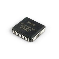
HCTL-1101 Avago Technologies US Inc., HCTL-1101 Datasheet - Page 34

HCTL-1101
Manufacturer Part Number
HCTL-1101
Description
IC MOTION CONTROL GP 40DIP
Manufacturer
Avago Technologies US Inc.
Datasheet
1.HCTL-1101.pdf
(40 pages)
Specifications of HCTL-1101
Applications
DC Motor Controller, Stepper Motor Controller
Voltage - Supply
4.75 V ~ 5.25 V
Operating Temperature
-20°C ~ 85°C
Mounting Type
Through Hole
Package / Case
40-DIP (0.600", 15.24mm)
Lead Free Status / RoHS Status
Lead free / RoHS Compliant
Current - Output
-
Number Of Outputs
-
Voltage - Load
-
Lead Free Status / Rohs Status
Lead free / RoHS Compliant
Available stocks
Company
Part Number
Manufacturer
Quantity
Price
Part Number:
HCTL-1101
Manufacturer:
AVAGO/安华高
Quantity:
20 000
Company:
Part Number:
HCTL-1101-PLC
Manufacturer:
Avago Technologies US Inc.
Quantity:
10 000
The units of acceleration are quadrature counts/sample
time squared. To convert from rpm/sec to
quadrature counts/[sample time]2, use the formula shown
below:
Where:
Aq = Acceleration in quadrature counts/[sample time]2
Ar = Acceleration in rpm/sec
N = 4 times the number of slots in the codewheel
T = The HCTL-1101 sample time in seconds.
(See the section on the HCTL-1101’s Sample Timer regis-
ter).
Because the Command Acceleration registers (R27H and
R26H) are internally interpreted by the HCTL-1101 as 8 bits
of integer and 8 bits of fraction, the host processor must
multiply the desired command acceleration (in quadra-
ture counts/[sample time]2) by 256 before programming
it into the HCTL-1101’s Command Acceleration registers.
Internally, the controller performs velocity profiling
through position control.
Figure 13. Integral Velocity Modes.
34
(i.e.,quadrature counts)
Each sample time, the internal profile generator uses the
information which the user has programmed into the
Command Velocity register (R3CH) and the Command Ac-
celeration registers (R27H and R26H) to determine the val-
ue which will be automatically loaded into the Command
Position registers (R0CH, R0DH, and R0EH). After the new
command position has been generated, the difference
between the values in the Actual Position registers (R12-
R13H, and R14H) and the new value in the Command Posi-
tion registers is calculated as the new position error. This
new position error is used by the full digital compensation
filter to compute a new motor command output by this
sample time. The register block in Figure 3 further shows
how the internal profile generator works in Integral Ve-
locity mode. In control theory terms, integral compensa-
tion has been added and there-fore, this system has zero
steady-state error.
Although Integral Velocity Control mode has the advan-
tage over Proportional Velocity mode of zero steady state
velocity error, its disadvantage is that the closed loop sta-
bility is more difficult to achieve. In Integral Velocity Con-
trol mode the system is actually a position control system
and therefore the complete dynamic compensation D(z)
is used.
If the external STOP flag F6 is set during this signaling an
emergency situation, the controller automatically deceler-
ates to zero velocity at the presently specified acceleration
factor and stays in this condition until the falg is cleared.
The user then can specify new velocity profiling data.


