VO3150A Vishay, VO3150A Datasheet - Page 2
VO3150A
Manufacturer Part Number
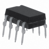
VO3150A
Description
IC DRIVER IGBT/MOSFET 0.5A 8-DIP
Manufacturer
Vishay
Type
High Side/Low Side Driverr
Datasheet
1.VO3150A-X007T.pdf
(10 pages)
Specifications of VO3150A
Isolation Voltage
5300 Vrms
Input Type
Non-Inverting
Number Of Outputs
1
Current - Output / Channel
500mA
Current - Peak Output
500mA
Voltage - Supply
15 V ~ 32 V
Operating Temperature
-40°C ~ 110°C
Mounting Type
Through Hole
Package / Case
8-DIP (0.300", 7.62mm)
Fall Time
0.1 us
Logic Gate Type
IGBT
Rise Time
0.1 us
Configuration
1 Channel
Output Type
Integrated Photo IC
Maximum Propagation Delay Time
0.4 us
Maximum Forward Diode Voltage
1.6 V
Minimum Forward Diode Voltage
1 V
Maximum Reverse Diode Voltage
5 V
Maximum Forward Diode Current
25 mA
Maximum Continuous Output Current
0.5 A
Maximum Power Dissipation
295 mW
Maximum Operating Temperature
+ 110 C
Minimum Operating Temperature
- 40 C
No. Of Channels
1
Optocoupler Output Type
Gate Drive
Input Current
16mA
Output Voltage
500mV
Opto Case Style
DIP
No. Of Pins
8
Output Current
0.5A
Lead Free Status / RoHS Status
Lead free / RoHS Compliant
On-state Resistance
-
Lead Free Status / Rohs Status
Lead free / RoHS Compliant
Available stocks
Company
Part Number
Manufacturer
Quantity
Price
Company:

Part Number:
VO3150A
Manufacturer:
Vishay Semiconductors
Quantity:
1 899


VO3150A
Vishay Semiconductors
Notes
(1)
(2)
(3)
www.vishay.com
2
ABSOLUTE MAXIMUM RATINGS
PARAMETER
INPUT
Input forward current
Peak transient input current
Reverse input voltage
Output power dissipation
OUTPUT
High peak output current
Low peak output current
Supply voltage
Output voltage
Output power dissipation
OPTOCOUPLER
Isolation test voltage
(between emitter and detector, climate
per DIN 500414, part 2, Nov. 74)
Storage temperature range
Ambient operating temperature range
Total power dissipation
Lead solder temperature
RECOMMENDED OPERATING CONDITION
PARAMETER
Power supply voltage
Input LED current (on)
Input voltage (off)
Operating temperature
Stresses in excess of the absolute maximum ratings can cause permanent damage to the device. Functional operation of the device is not
implied at these or any other conditions in excess of those given in the operational sections of this document. Exposure to absolute
maximum ratings for extended periods of the time can adversely affect reliability.
Maximum pulse width = 10 μs, maximum duty cycle = 0.2 %. This value is intended to allow for component tolerances for designs with
I
Refer to reflow profile for soldering conditions for surface mounted devices (SMD). Refer to wave profile for soldering conditions for through
hole devices (DIP).
O
peak minimum = 0.5 A. See applications section for additional details on limiting I
(2)
(3)
(2)
For technical questions, contact:
for 10 s, 1.6 mm below seating plane
0.5 A Output Current IGBT and
< 1 μs pulse width, 300 pps
(1)
(T
TEST CONDITION
SYMBOL
V
amb
CC
V
T
F(OFF)
amb
I
- V
F
t = 1 s
MOSFET Driver
= 25 °C, unless otherwise specified)
EE
optocoupleranswers@vishay.com
MIN.
- 40
- 3
15
7
(V
OH
SYMBOL
I
I
V
OH(PEAK)
I
OL(PEAK)
CC
F(TRAN)
O(PEAK)
P
P
T
V
P
T
peak.
V
T
amb
I
diss
diss
ISO
sld
F
- V
tot
R
S
EE
)
- 55 to + 125
- 40 to + 110
MAX.
+ 110
0 to + V
0.8
32
16
0 to + 35
VALUE
5300
250
295
260
0.5
0.5
25
45
1
5
CC
Document Number: 81808
Rev. 1.1, 14-Jan-10
UNIT
mA
UNIT
V
°C
mW
mW
mW
V
V
mA
°C
°C
°C
RMS
A
A
A
V
V
V
Related parts for VO3150A
Image
Part Number
Description
Manufacturer
Datasheet
Request
R

Part Number:
Description:
357-036-542-201 CARDEDGE 36POS DL .156 BLK LOPRO
Manufacturer:
Vishay
Datasheet:
Part Number:
Description:
357-036-542-201 CARDEDGE 36POS DL .156 BLK LOPRO
Manufacturer:
Vishay
Datasheet:
Part Number:
Description:
357-036-542-201 CARDEDGE 36POS DL .156 BLK LOPRO
Manufacturer:
Vishay
Datasheet:
Part Number:
Description:
357-036-542-201 CARDEDGE 36POS DL .156 BLK LOPRO
Manufacturer:
Vishay
Datasheet:
Part Number:
Description:
357-036-542-201 CARDEDGE 36POS DL .156 BLK LOPRO
Manufacturer:
Vishay
Datasheet:
Part Number:
Description:
357-036-542-201 CARDEDGE 36POS DL .156 BLK LOPRO
Manufacturer:
Vishay
Datasheet:
Part Number:
Description:
357-036-542-201 CARDEDGE 36POS DL .156 BLK LOPRO
Manufacturer:
Vishay
Datasheet:
Part Number:
Description:
357-036-542-201 CARDEDGE 36POS DL .156 BLK LOPRO
Manufacturer:
Vishay
Datasheet:
Part Number:
Description:
357-036-542-201 CARDEDGE 36POS DL .156 BLK LOPRO
Manufacturer:
Vishay
Datasheet:
Part Number:
Description:
357-036-542-201 CARDEDGE 36POS DL .156 BLK LOPRO
Manufacturer:
Vishay
Datasheet:
Part Number:
Description:
357-036-542-201 CARDEDGE 36POS DL .156 BLK LOPRO
Manufacturer:
Vishay
Datasheet:
Part Number:
Description:
357-036-542-201 CARDEDGE 36POS DL .156 BLK LOPRO
Manufacturer:
Vishay
Datasheet:
Part Number:
Description:
357-036-542-201 CARDEDGE 36POS DL .156 BLK LOPRO
Manufacturer:
Vishay
Datasheet:
Part Number:
Description:
357-036-542-201 CARDEDGE 36POS DL .156 BLK LOPRO
Manufacturer:
Vishay
Datasheet:
Part Number:
Description:
357-036-542-201 CARDEDGE 36POS DL .156 BLK LOPRO
Manufacturer:
Vishay
Datasheet: