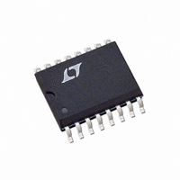
LT1158ISW#TRPBF Linear Technology, LT1158ISW#TRPBF Datasheet - Page 3

LT1158ISW#TRPBF
Manufacturer Part Number
LT1158ISW#TRPBF
Description
IC MOSFET DVR 1/2BRDG NCH 16SOIC
Manufacturer
Linear Technology
Datasheet
1.LT1158CNPBF.pdf
(22 pages)
Specifications of LT1158ISW#TRPBF
Configuration
Half Bridge
Input Type
PWM
Current - Peak
500mA
Number Of Configurations
1
Number Of Outputs
2
High Side Voltage - Max (bootstrap)
56V
Voltage - Supply
5 V ~ 30 V
Operating Temperature
-40°C ~ 85°C
Mounting Type
Surface Mount
Package / Case
16-SOIC (0.300", 7.5mm Width)
Lead Free Status / RoHS Status
Lead free / RoHS Compliant
Delay Time
-
Available stocks
Company
Part Number
Manufacturer
Quantity
Price
ELECTRICAL CHARACTERISTICS
temperature range, otherwise specifi cations are at T
Gate Feedback pins connected to Gate Drive pins unless otherwise specifi ed.
SYMBOL
I
I
V6
I
V4
ΔV4
I
V15
V9
V1
V14 – V13 Top Turn-Off Threshold
V8
I
V5
V12 – V11 Fault Conduction Threshold
V12 – V11 Current Limit Threshold
V12 – V11 Current Limit Inhibit
t
t
t
t
t
t
Note 1: Stresses beyond those listed under Absolute Maximum Ratings
may cause permanent damage to the device. Exposure to any Absolute
Maximum Rating condition for extended periods may affect device
reliability and lifetime.
Note 2: T
dissipation P
LT1158IN, LT1158CN: T
LT1158ISW, LT1158CSW: T
2
16
6
4
5
R
D
F
R
D
F
+ I
10
J
is calculated from the ambient temperature T
PARAMETER
DC Supply Current (Note 2)
Boost Current
Input Threshold
Input Current
Enable Low Threshold
Enable Hysteresis
Enable Pullup Current
Charge Pump Voltage
Bottom Gate “ON” Voltage
Boost Drive Voltage
Bottom Turn-Off Threshold
Fault Output Leakage
Fault Output Saturation
V
Top Gate Rise Time
Top Gate Turn-Off Delay
Top Gate Fall Time
Bottom Gate Rise Time
Bottom Gate Turn-Off Delay
Bottom Gate Fall Time
D
DS
according to the following formulas:
Threshold
J
= T
J
A
= T
+ (P
A
+ (P
D
× 70°C/W)
D
× 110°C/W)
CONDITIONS
V
V
V
V
V6 = 5V
V6 = 0.8V, Monitor V9
V6 = 0.8V, Monitor V9
V4 = 0V
V
V
V
V
V
V
V
V
V
V
V
Until V15 Goes Low
Pin 6 (+) Transition, Meas. V15 – V13 (Note 4)
Pin 6 (–) Transition, Meas. V15 – V13 (Note 4)
Pin 6 (–) Transition, Meas. V15 – V13 (Note 4)
Pin 6 (–) Transition, Meas. V9 (Note 4)
Pin 6 (+) Transition, Meas. V9 (Note 4)
Pin 6 (+) Transition, Meas. V9 (Note 4)
+
+
+
+
+
+
+
+
+
+
+
+
+
+
+
= 30V, V16 = 15V, V4 = 0.5V
= 30V, V16 = 15V, V6 = 0.8V
= 30V, V16 = 15V, V6 = 2V
= V13 = 30V, V16 = 45V, V6 = 0.8V
= 5V, V6 = 2V, Pin 16 open, V13 → 5V
= 30V, V6 = 2V, Pin16 open, V13 → 30V
= V16 = 18V, V6 = 0.8V
= V16 = 18V, V6 = 0.8V, 100mA Pulsed Load
= V16 = 5V, V6 = 0.8V
= V16 = 5V, V6 = 2V
= 30V, V16 = 15V, V6 = 2V
= 30V, V16 = 15V, V6 = 2V, I
= 30V, V16 = 15V, V6 = 2V, I
= 30V, V16 = 15V, V6 = 2V, Closed Loop
= V12 = 12V, V6 = 2V, Decrease V11
A
and power
A
= 25°C. Test Circuit, V
The
l
5
5
denotes the specifi cations which apply over the full operating
= 10mA
= 100μA
Note 3: Dynamic supply current is higher due to the gate charge
being delivered at the switching frequency. See typical performance
characteristics and applications information.
Note 4: Gate rise times are measured from 2V to 10V, delay times are
measured from the input transition to when the gate voltage has decreased
to 10V, and fall times are measured from 10V to 2V.
+
= V16 = 12V, V11 = V12 = V13 = 0V, Pins 1 and 4 open,
l
l
l
l
l
l
l
l
l
l
l
l
l
l
l
l
l
MIN
130
120
4.5
0.8
0.9
1.3
1.1
15
40
12
12
90
8
9
1
1
LT1158I
1.15
14.5
14.5
1.75
1.25
TYP
110
150
130
350
120
130
200
100
2.2
1.4
1.5
1.5
0.1
0.5
13
25
11
43
7
3
5
MAX
130
170
180
250
550
250
250
400
200
4.5
1.4
1.7
2.5
1.4
10
18
15
35
47
17
17
3
2
2
1
1
0.85
MIN
120
120
4.5
0.8
1.2
1.1
15
40
12
12
85
8
9
1
1
LT1158C
1.15
14.5
14.5
1.75
1.25
TYP
110
150
130
350
120
130
200
100
2.2
1.4
1.5
1.5
0.1
0.5
13
25
11
43
7
3
5
LT1158
MAX
135
180
180
250
550
250
250
400
200
4.5
1.4
1.8
2.5
1.4
10
18
15
35
47
17
17
3
2
2
1
1
UNITS
1158fb
3
mA
mA
mA
mA
mV
mV
mV
μA
μA
μA
ns
ns
ns
ns
ns
ns
V
V
V
V
V
V
V
V
V
V
V


