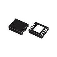
L6747CTR STMicroelectronics, L6747CTR Datasheet

L6747CTR
Specifications of L6747CTR
Related parts for L6747CTR
L6747CTR Summary of contents
Page 1
... Combined with ST PWM controllers, the driver allows the implementation of complete voltage Table 1. Device summary Order codes L6747C L6747CTR April 2010 High current MOSFET driver VFDFPN8 3x3 mm regulator solutions for modern high-current CPUs and for DC-DC conversion in general. The L6747C embeds high-current drivers for both high-side and low-side MOSFETS ...
Page 2
Contents Contents 1 Typical application circuit and block diagram . . . . . . . . . . . . . . . . . . . . 3 2 Pin information and thermal data . . . . ...
Page 3
L6747C 1 Typical application circuit and block diagram Figure 1. L6747C typical application circuit 12V CC C PWM Input EN Input L6747C Reference Schematic Figure 2. L6747C block diagram VCC EN 70k PWM 7k Typical application ...
Page 4
Pin information and thermal data 2 Pin information and thermal data 2.1 Pin information Figure 3. Pin connection diagram (top view) Table 2. Pin descriptions Pin # Name 1 BOOT 2 PWM VCC 5 LGATE 6 GND ...
Page 5
L6747C Table 2. Pin descriptions (continued) Pin # Name 8 UGATE - TH. PAD 2.2 Thermal data Table 3. Thermal data Symbol Thermal resistance junction-to-ambient R THJA (device soldered on 2s2p, 67mm x 69mm board) R Thermal resistance junction-to-case THJC ...
Page 6
Electrical specifications 3 Electrical specifications 3.1 Absolute maximum ratings Table 4. Absolute maximum ratings Symbol V to GND CC to GND V to GND, t < 200 ns BOOT to PHASE V UGATE t < 200 ns to GND V ...
Page 7
L6747C Table 5. Electrical characteristics (continued) Symbol Parameter PWM and EN INPUT Input high - V PWM_IH PWM Input low - V PWM_IL Input leakage t HiZ hold-off time HiZ t prop_L Propagation delays t prop_H Input High - V ...
Page 8
Device description and operation 4 Device description and operation The L6747C provides high-current driving control for both high-side and low-side N-channel MOSFETs, connected as step-down DC-DC converters and driven by an external PWM signal. The integrated high-current drivers allow the ...
Page 9
L6747C 4.1 High-impedance (HiZ) management The driver is capable of managing a high-impedance conditions by keeping all MOSFETs in an OFF state. This is achieved in two different ways: ● If the EN signal is pulled low, the device keeps ...
Page 10
Device description and operation To prevent the bootstrap capacitor from overcharging as a consequence of large negative spikes, an external series R series with the BOOT pin. Figure 5. Bootstrap capacitance design 2.5 Cboot = 47nF Cboot = 100nF 2.0 ...
Page 11
L6747C MOSFET to reach the driving voltage (PVCC for HS and VCC for LS). This capacitor is charged and discharged at the driver switching frequency F The total power P driving path. According to the external gate resistance and the ...
Page 12
Device description and operation (VCC, PVCC and BOOT capacitors) close to the device with the shortest possible loop, using wide copper traces to minimize parasitic inductance. Systems that do not use Schottky diodes in parallel with the low-side MOSFET might ...
Page 13
L6747C 5 Package mechanical data In order to meet environmental requirements, ST offers these devices in different grades of ® ECOPACK packages, depending on their level of environmental compliance. ECOPACK specifications, grade definitions and product status are available at: www.st.com. ...
Page 14
Revision history 6 Revision history Table 6. Document revision history Date 23-Apr-2010 14/15 Revision 1 Initial release. Doc ID 17127 Rev 1 L6747C Changes ...
Page 15
... L6747C Information in this document is provided solely in connection with ST products. STMicroelectronics NV and its subsidiaries (“ST”) reserve the right to make changes, corrections, modifications or improvements, to this document, and the products and services described herein at any time, without notice. All ST products are sold pursuant to ST’s terms and conditions of sale. ...


