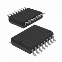
UBA2025T/N1,518 NXP Semiconductors, UBA2025T/N1,518 Datasheet - Page 4

UBA2025T/N1,518
Manufacturer Part Number
UBA2025T/N1,518
Description
IC DRIVER HALF BRIDGE 16-SOIC
Manufacturer
NXP Semiconductors
Type
CFL/TL Driverr
Specifications of UBA2025T/N1,518
Package / Case
16-SOIC (0.300", 7.5mm Width)
Frequency
42.21 ~ 44.59 kHz
Current - Supply
1.6mA
Current - Output
1.5A
Operating Temperature
-40°C ~ 150°C
Driver Type
CFL Drivers
Operating Supply Voltage
600 V
Maximum Operating Temperature
+ 150 C
Mounting Style
SMD/SMT
Maximum Output Current
1.5 A
Minimum Operating Temperature
- 40 C
Supply Current
1.6 mA
Lead Free Status / RoHS Status
Lead free / RoHS Compliant
Voltage - Supply
-
Lead Free Status / Rohs Status
Lead free / RoHS Compliant
Other names
568-4923-2
935287838518
935287838518
NXP Semiconductors
7. Functional description
UBA2025_1
Product data sheet
7.1 Introduction
7.2 Initial start-up
7.3 Oscillation
7.4 Operation in preheat mode
The IC is an integrated circuit for electronically ballasted compact fluorescent lamps and
its derivatives, up to a nominal mains voltage of 230 V (RMS). It provides all the
necessary functions for proper preheat, ignition and on-state operation of the lamp.
Besides the control function, the IC provides the level shift and drive for the two internal
power MOSFETs.
Initial start-up is achieved by charging CS9 (see
pin RHV. The start-up of the circuit is such that (see
T1 shall be non-conductive, in order to make sure that C
state is reached for a supply voltage V
circuit will be reset to the initial state and maintained until the low voltage supply (V
reaches a value of V
If the low voltage supply (V
in the preheat state. The internal oscillator is a current-controlled circuit which generates a
sawtooth waveform. The frequency of the sawtooth is determined by the capacitor CF and
the current out of pin CF (mainly set by R
frequency of the signal across the load. The IC brings alternately the power MOSFETs
T1 and T2 into conduction with a duty cycle of approximately 50%.
the timing of the IC. The circuit block 'non-overlap' generates a non-overlap time t
T1 and T2 are not conducting. This is dependent on the reference current.
The circuit starts oscillating at a frequency of approximately 2.5f
frequency will gradually decrease until a defined value of the current through R
reached (see
Fig 3.
Oscillator timing
Figure
startup
4). The slope of the decrease in frequency is determined by the
V
Rev. 01 — 16 October 2009
internal
(GT1-S1)
V
clock
V
(GT2)
CF
.
VS
0
0
0
0
) has reached the value of V
start-up
rst
, this is the voltage level at pin VS at which the
IREF
t
no
). The sawtooth frequency is twice the
Figure
Figure
6) with the current applied to
BOOT
startup
t
no
1) T2 shall be conductive and
time
gets charged. This start-up
the circuit starts oscillating
mgs991
btm
Figure 3
(108 kHz). The
UBA2025
© NXP B.V. 2009. All rights reserved.
CFL power IC
represents
SHUNT
no
VS
when
4 of 17
)
is


