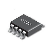
CY8CLEDAC02 Cypress Semiconductor Corp, CY8CLEDAC02 Datasheet - Page 6

CY8CLEDAC02
Manufacturer Part Number
CY8CLEDAC02
Description
IC CTLR AC-DC DIMMABLE LED 8SOIC
Manufacturer
Cypress Semiconductor Corp
Type
High Power, AC Input, Dimmabler
Datasheet
1.CY8CLEDAC02.pdf
(20 pages)
Specifications of CY8CLEDAC02
Package / Case
8-SOIC (3.9mm Width)
Voltage - Supply
8 V ~ 16 V
Frequency
200kHz
Operating Temperature
-40°C ~ 85°C
Number Of Outputs
1
Internal Switch(s)
No
Efficiency
85%
Topology
AC DC Offline Switcher
Operating Supply Voltage
- 0.3 V to 18 V
Maximum Supply Current
20 mA
Maximum Power Dissipation
526 mW
Maximum Operating Temperature
+ 85 C
Mounting Style
SMD/SMT
Minimum Operating Temperature
- 40 C
Operating Temperature (min)
-40C
Operating Temperature (max)
85C
Operating Temperature Classification
Industrial
Pin Count
8
Mounting
Surface Mount
Operating Supply Voltage (max)
18V
Lead Free Status / RoHS Status
Lead free / RoHS Compliant
Voltage - Output
-
Current - Output / Channel
-
Lead Free Status / Rohs Status
Lead free / RoHS Compliant
Available stocks
Company
Part Number
Manufacturer
Quantity
Price
Company:
Part Number:
CY8CLEDAC02
Manufacturer:
TI
Quantity:
900
Part Number:
CY8CLEDAC02
Manufacturer:
CYPRESS/赛普拉斯
Quantity:
20 000
Figure 3. Device Startup Sequencing
Dimmer Detection
Intelligent Wall Dimmer detection includes automatically
detecting presence or absence of a dimmer and, if present,
detecting the dimmer type (leading or trailing edge).
Dimmer detection or discovery takes place during the first four
AC half cycles after startup. During this phase the BOOST pin
remains high, placing a purely resistive load across the dimmer.
As wall dimmers are designed to work with resistive loads such
Document Number: 001-54879 Rev. *C
Figure 4. AC Line Waveforms with Leading Edge (left) and Trailing Edge (right) Dimmers
AC line before Wall-
dimmer
Dimmed AC line after
Wall-dimmer
as an incandescent lamp, loading the dimmer with a purely
resistive load enables accurate dimmer detection.
The operation is broken into two stages. In the first stage, the
controller simply determines whether a dimmer is present. If a
dimmer is not detected, the dimmer type is set to 'no dimmer'. If
a dimmer is detected, then in the next stage the dimmer type
(leading or trailing edge) is determined.
The presence or absence of a dimmer is determined by
monitoring how long the V
detect (ZCD) threshold. This threshold is determined by the
controller using the peak of line and half line period measure-
ments. An internal digital signal, V
tracks the V
t
on page 7). This detection scheme is based on the fact that V
will remain below the ZCD threshold for a much longer duration
in a single AC half cycle when a dimmer is present. In most cases
V
the line. In cases when the dimmer does not exhibit any phase
cut (at maximum setting) the duration is longer due to delays
associated with dimmer operation.
If a dimmer is detected, then the V
differentiated to identify the largest positive and negative slopes
in the AC half cycle. If the positive (rising) slope is greater than
1.5 times the negative (falling) slope, then a leading edge
dimmer must be present. If not, a trailing edge dimmer must be
present.
CROSS
IN
is below the ZCD threshold for longer due to phase cut on
) for which V
IN
signal and determines the duration (t
AC line before Wall-
IN
dimmer
is below the ZCD threshold (see
IN
Dimmed AC line after
voltage stays below a zero-cross
Wall-dimmer
IN
CROSS,
CY8CLEDAC02
pin voltage is filtered and
is generated which
Page 6 of 20
PERIOD
Figure 5
IN
–
[+] Feedback


