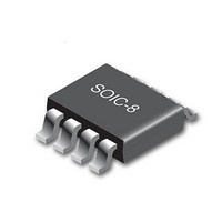
CY8CLEDAC02 Cypress Semiconductor Corp, CY8CLEDAC02 Datasheet - Page 10

CY8CLEDAC02
Manufacturer Part Number
CY8CLEDAC02
Description
IC CTLR AC-DC DIMMABLE LED 8SOIC
Manufacturer
Cypress Semiconductor Corp
Type
High Power, AC Input, Dimmabler
Datasheet
1.CY8CLEDAC02.pdf
(20 pages)
Specifications of CY8CLEDAC02
Package / Case
8-SOIC (3.9mm Width)
Voltage - Supply
8 V ~ 16 V
Frequency
200kHz
Operating Temperature
-40°C ~ 85°C
Number Of Outputs
1
Internal Switch(s)
No
Efficiency
85%
Topology
AC DC Offline Switcher
Operating Supply Voltage
- 0.3 V to 18 V
Maximum Supply Current
20 mA
Maximum Power Dissipation
526 mW
Maximum Operating Temperature
+ 85 C
Mounting Style
SMD/SMT
Minimum Operating Temperature
- 40 C
Operating Temperature (min)
-40C
Operating Temperature (max)
85C
Operating Temperature Classification
Industrial
Pin Count
8
Mounting
Surface Mount
Operating Supply Voltage (max)
18V
Lead Free Status / RoHS Status
Lead free / RoHS Compliant
Voltage - Output
-
Current - Output / Channel
-
Lead Free Status / Rohs Status
Lead free / RoHS Compliant
Available stocks
Company
Part Number
Manufacturer
Quantity
Price
Company:
Part Number:
CY8CLEDAC02
Manufacturer:
TI
Quantity:
900
Part Number:
CY8CLEDAC02
Manufacturer:
CYPRESS/赛普拉斯
Quantity:
20 000
switching resumes if the fault is removed and the OCP threshold
is not reached.
Single Point Fault Protection
The CY8CLEDAC02 can detect a short on any of the following
pins V
single point fault is protected against.
Understanding Primary Feedback
Figure 11
switch Q1 conducts during t
drawn from rectified sinusoid v
the magnetizing inductance L
reverse biased and the load current I
secondary capacitor C
the stored energy E
Figure 11. Simplified Flyback Converter
To tightly regulate output current, information about the load
current needs to be accurately sensed. To achieve CC
regulation, this information can be derived indirectly by sensing
the primary current.
To detect faults with output voltage, information about the output
voltage and load current needs to be accurately sensed. In the
DCM flyback converter, this information can be read through the
auxiliary winding.
During the Q1 on time, the load current is supplied from the
output filter capacitor C
Document Number: 001-54879 Rev. *C
v
in
(t)
IN
i
in
(t)
, I
SENSE
illustrates a simplified flyback converter. When the
, V
SENSE
g
AC
AC
(t) is delivered to the output.
O
+
_
. When Q1 turns off, D1 conducts and
, V
O
. The voltage across L
CC
v
ON
g
, OUTPUT, and V
(t)
T
g
i
s
g
(t)
(t) . The energy E
P
(t)
(t) , the current i
. The rectifying diode D1 is
L
N
AUX
AUX
N
L
Q1
P
P
O
N
L
S
S
is supplied by the
D1
T
. Therefore any
g
g
(t) is stored in
(t) is directly
i
d
(t)
P
is v
+
C
o
g
V
(t) ,
o
I
o
assuming the voltage dropped across Q1 is zero. The current in
Q1 ramps up linearly at a rate of:
Equation 4
At the end of on time, the current has ramped up to:
Equation 5
This current represents a stored energy of:
Equation 6
When Q1 turns off, i
windings. Ignoring the commutation time caused by the leakage
inductance L
transfers to the secondary at a peak amplitude of:
Equation 7
Assuming the secondary winding is master and the auxiliary
winding is slave, the auxiliary voltage is given by:
Equation 8
and reflects the output voltage as shown in
V
i
i
E
d
di
g
AUX
_
g
) (
dt
t
g
peak
(
t
)
L
) (
2
t
P
N
N
N
N
AUX
P
S
v
KP
S
g
L
i
v
) (
g
P
t
at the instant of turn-off, the primary current
i
g
(
_
V
g
) (
peak
t
_
O
g
L
(t) in L
peak
P
) (
t
t
ON
) (
V
t
2
P
)
forces a reversal of polarities on all
CY8CLEDAC02
Figure 12 on page
Page 10 of 20
11.
[+] Feedback


