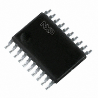
PCA9634PW,118 NXP Semiconductors, PCA9634PW,118 Datasheet - Page 19

PCA9634PW,118
Manufacturer Part Number
PCA9634PW,118
Description
IC LED DRIVER RGBA 20-TSSOP
Manufacturer
NXP Semiconductors
Type
RGBA LED Driverr
Datasheet
1.PCA9634D118.pdf
(38 pages)
Specifications of PCA9634PW,118
Package / Case
20-TSSOP
Topology
Open Drain, PWM
Number Of Outputs
8
Internal Driver
Yes
Type - Primary
Backlight, LED Blinker
Type - Secondary
RGBA
Frequency
1MHz
Voltage - Supply
2.3 V ~ 5.5 V
Voltage - Output
5.5V
Mounting Type
Surface Mount
Operating Temperature
-40°C ~ 85°C
Current - Output / Channel
25mA
Internal Switch(s)
Yes
Low Level Output Current
25 mA
High Level Output Current
50 uA
Operating Supply Voltage
2.3 V to 5.5 V
Maximum Supply Current
10 mA
Maximum Power Dissipation
400 mW
Maximum Operating Temperature
+ 85 C
Mounting Style
SMD/SMT
Minimum Operating Temperature
- 40 C
Lead Free Status / RoHS Status
Lead free / RoHS Compliant
Efficiency
-
Lead Free Status / Rohs Status
Lead free / RoHS Compliant
Other names
568-4066-2
935282233118
PCA9634PW-T
PCA9634PW-T
935282233118
PCA9634PW-T
PCA9634PW-T
NXP Semiconductors
PCA9634_6
Product data sheet
Fig 8.
1
1
Brightness Control signal (LEDn)
Group Dimming signal
resulting Brightness + Group Dimming signal
2
2
(GRPPWM Register)
M
Minimum pulse width for LEDn Brightness Control is 40 ns.
Minimum pulse width for Group Dimming is 20.48 s.
When M = 1 (GRPPWM register value), the resulting LEDn Brightness Control + Group Dimming signal will have 2 pulses of
the LED Brightness Control signal (pulse width = N
This resulting Brightness + Group Dimming signal above shows a resulting Control signal with M = 4 (8 pulses).
Brightness + Group Dimming signals
with M = (0 to 255)
3
3
256
4
4
7.8 Individual brightness control with group dimming/blinking
2
5
5
40 ns
6
6
A 97 kHz fixed frequency signal with programmable duty cycle (8 bits, 256 steps) is used
to control individually the brightness for each LED.
On top of this signal, one of the following signals can be superimposed (this signal can be
applied to the 4 LED outputs):
7
7
•
•
256
8
8
A lower 190 Hz fixed frequency signal with programmable duty cycle (8 bits,
256 steps) is used to provide a global brightness control.
A programmable frequency signal from 24 Hz to
programmable duty cycle (8 bits, 256 steps) is used to provide a global blinking
control.
9 10 11 12
2
256
40 ns = 5.24 ms (190.7 Hz)
Rev. 06 — 12 September 2008
256
(97.6 kHz)
40 ns = 10.24 s
40 ns, with ‘N’ defined in PWMx register).
N
with N = (0 to 255)
(PWMx Register)
40 ns
507
508
509
510
511
512
1
10.73
1
1
2
2
8-bit Fm+ I
Hz (8 bits, 256 steps) with
3
3
4
4
5
5
6
6
PCA9634
2
© NXP B.V. 2008. All rights reserved.
C-bus LED driver
7
7
8
8
9 10 11
002aab417
19 of 38


