LTC3783EDHD#TRPBF Linear Technology, LTC3783EDHD#TRPBF Datasheet - Page 9
LTC3783EDHD#TRPBF
Manufacturer Part Number
LTC3783EDHD#TRPBF
Description
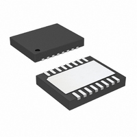
IC LED DRIVER PWM CONTROL 16-DFN
Manufacturer
Linear Technology
Type
PWM Controlr
Datasheet
1.LTC3783EFEPBF.pdf
(24 pages)
Specifications of LTC3783EDHD#TRPBF
Constant Current
Yes
Constant Voltage
Yes
Topology
Flyback, PWM, SEPIC, Step-Down (Buck), Step-Up (Boost)
Number Of Outputs
1
Internal Driver
No
Type - Primary
Automotive, General Purpose
Frequency
20kHz ~ 1MHz
Voltage - Supply
3 V ~ 36 V
Mounting Type
Surface Mount
Package / Case
16-DFN
Operating Temperature
-40°C ~ 85°C
Internal Switch(s)
No
Lead Free Status / RoHS Status
Lead free / RoHS Compliant
Voltage - Output
-
Current - Output / Channel
-
Efficiency
-
Available stocks
Company
Part Number
Manufacturer
Quantity
Price


OPERATION
Main Control Loop
The LTC3783 is a constant frequency, current mode con-
troller for PWM LED as well as DC/DC boost, SEPIC and
fl yback converter applications. In constant current LED
applications, the LTC3783 provides an especially wide PWM
dimming range due to its unique switching scheme, which
allows PWM pulse widths as short as several converter
switching periods.
For voltage feedback circuit operation (defi ned by V
1.23V), please refer to the Block Diagram of the IC and the
Typical Application on the fi rst page of this data sheet. In
normal operation with PWMIN high, the power MOSFET
is turned on (GATE goes high) when the oscillator sets
the PWM latch, and is turned off when the ITRIP current
comparator resets the latch. Based on the error voltage
represented by (V
signal at the I
threshold. When the load current increases, a fall in the
FBN voltage relative to the reference voltage at FBP causes
the I
to trip at a higher peak inductor current value. The average
inductor current will therefore rise until it equals the load
current, thereby maintaining output regulation.
When PWMIN goes low, PWMOUT goes low, the I
opens and GATE switching is disabled. Lowering PWMOUT
and disabling GATE causes the output capacitor C
hold the output voltage constant in the absence of load
current. Opening the I
current value on the I
PWMIN goes high again, both I
at the appropriate levels.
In voltage feedback operation, an overvoltage compara-
tor, OV, senses when the OV/FB pin exceeds the reference
voltage by 7% and provides a reset pulse to the main RS
latch. Because this RS latch is reset-dominant, the power
MOSFET is actively held off for the duration of an output
overvoltage condition.
TH
pin to rise, causing the ITRIP current comparator
TH
pin sets the ITRIP current comparator input
FBP
TH
– V
TH
capacitor C
FBN
switch stores the correct load
), the error amplifi er output
TH
and V
ITH
. As a result, when
OUT
are instantly
TH
switch
OUT
FBP
to
≤
For constant current/constant voltage regulation operation
(defi ned by V
of the IC and Figure 11. Loop operation is similar to the
voltage feedback, except FBP and FBN now sense the
voltage across sense resistor R
The I
ferential set voltage, from 10mV to 100mV, for I
of 0.123V to 1.23V. That is, with V
will regulate such that V
of I
still functional as above, but will only work properly if load
current can be disconnected by the PWMOUT signal.
In constant current/constant voltage operation, the OV/FB
pin becomes a voltage feedback pin, which causes the loop
to regulate such that V
current-sense voltage is not reached. In this way, the loop
regulates either voltage or current, whichever parameter
hits its preset limit fi rst.
The nominal operating frequency of the LTC3783 is pro-
grammed using a resistor from the FREQ pin to ground
and can be controlled over a 20kHz to 1MHz range. In
addition, the internal oscillator can be synchronized to an
external clock applied to the SYNC pin and can be locked
to a frequency between 100% and 130% of its nominal
value. When the SYNC pin is left open, it is pulled low by
an internal 100k resistor. With no load, or an extremely
light one, the controller will skip pulses in order to maintain
regulation and prevent excessive output ripple.
The RUN pin controls whether the IC is enabled or is in a
low current shutdown state. A micropower 1.248V refer-
ence and RUN comparator allow the user to program the
supply voltage at which the IC turns on and off (the RUN
comparator has 100mV of hysteresis for noise immunity).
With the RUN pin below 1.248V, the chip is off and the
input supply current is typically only 20μA.
LIM
TH
attenuate the difference proportionally. PWMIN is
pin now represents the error from the desired dif-
FBP
> 2.5V), please refer to the Block Diagram
OV/FB
FBP
– V
= 1.23V, provided the above
FBN
L
in series with the load.
= 100mV; lower values
ILIM
LTC3783
= 1.23V, the loop
LIM
values
3783fb
9
Related parts for LTC3783EDHD#TRPBF
Image
Part Number
Description
Manufacturer
Datasheet
Request
R

Part Number:
Description:
Full-Featured LED Driver with 1.5A Switch Current
Manufacturer:
LINER [Linear Technology]
Datasheet:

Part Number:
Description:
CD ROM LINEARVIEW DATASHEETS
Manufacturer:
Linear Technology

Part Number:
Description:
Standalone Linear Li-Ion Battery Charger with Thermal Regulation in ThinSOT
Manufacturer:
Linear Technology Corporation
Datasheet:
Part Number:
Description:
Low noise, high frequency, 8th order linear phase lowpass filter
Manufacturer:
Linear Technology Corporation
Datasheet:
Part Number:
Description:
Manufacturer:
Linear Technology Corporation
Datasheet:
Part Number:
Description:
Manufacturer:
Linear Technology Corporation
Datasheet:
Part Number:
Description:
Manufacturer:
Linear Technology Corporation
Datasheet:
Part Number:
Description:
Manufacturer:
Linear Technology Corporation
Datasheet:
Part Number:
Description:
Manufacturer:
Linear Technology Corporation
Datasheet:
Part Number:
Description:
Manufacturer:
Linear Technology Corporation
Datasheet:
Part Number:
Description:
Manufacturer:
Linear Technology Corporation
Datasheet:
Part Number:
Description:
Dual and Quad, JFET Input Precision High Speed Op Amps
Manufacturer:
Linear Technology Corporation
Datasheet:
Part Number:
Description:
Manufacturer:
Linear Technology Corporation
Datasheet:
Part Number:
Description:
1, 2, 6 and 8 Channel, 10-Bit Serial I/O Data Acquisition Systems
Manufacturer:
Linear Technology Corporation
Datasheet:
Part Number:
Description:
Manufacturer:
Linear Technology Corporation
Datasheet: